flatdog
-
Posts
30 -
Joined
-
Last visited
Content Type
Profiles
Forums
Events
Gallery
Downloads
Everything posted by flatdog
-
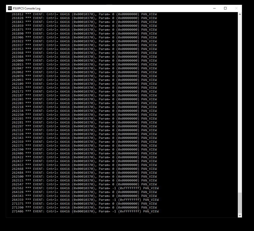
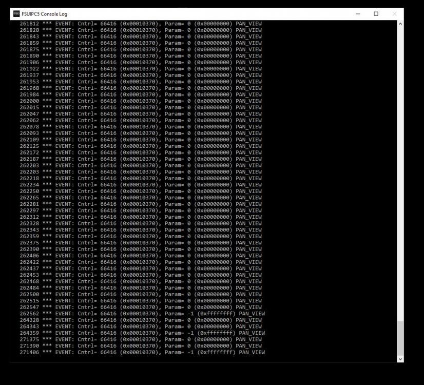
I am using FSUIPC 5.153 (Registered) and P3D Version 4.5.12.30293. For some reason the virtual cockpit view has started panning up when I load a scenario. I don't have any button, key or axis assignments in FSUIPC as I am using ProSim 737. All axis and button assignments have been removed from P3D. I have attached a copy of the log window. I have tried disconnecting yokes and keyboard without success. Any ideas would be very welcome. Screen capture of log console attached. Thank you.
-
Dear Pete, I just bought a second hand 737 throttle quadrant and was rather dreading setting it all up, especially the flaps. I assigned all the axes directly through FSUIPC and then calibrated them. FSUIPC could see that I was using the Jetstream 737 flight model (used with ProSim 737) and adjusted accordingly. Everything works perfectly and all in about 20 minutes. I don't mean to sound surprised but things don't often go like that with cockpit building as I am sure you are aware. Many thanks for helping to make things easier. kind regards, Philip
-
OK - many thanks, Philip
-
Dear Pete, There are six pins on the card that can be used as PWM outputs, channel 5 refers to pin 17. The other information in the manual is: SetPWMOutputs Set complete PWM outputs configuration bool SetPWMOutputs(ref bool[] channels, ref uint period, ref uint[] duty_values); Arguments: channels An array of 6 boolean values, each representing one PWM channel. Channel is enabled if this value is set to true. period 32-bit PWM period value. PWM module of a PoKeys55 device runs at 12 Mhz, so a value of 12 000 000 produces a period of 1 second. PWM module on PoKeys56E devices runs at 25 MHz, so a value of 25 000 000 produces a period of 1 second. duty_values An array of 6 32-bit unsigned integers, each representing the value of PWM duty for each channel. Minimum value is 0, maximum value is the same as period. Channel to pin mapping: Channels are mapping according to this table: Channel PoKeys pin 0 22 1 21 2 20 3 19 4 18 5 17 The PoKeys website does not appear to have a user forum. I will ask over at myCockpit to see if anyone knows of a user group. Many thanks, Philip
-
Dear Pete, I have been using the sample lua script posted by Terry Hall to interface with a PoKeys56U card. I have added some switches and LEDs for various functions which all seem to work so I feel I have a reasonable understanding of what is happening. I would now like to use the PWM output(s) of the card to build a simple three position flaps gauge incorporating a servo. The example in the PoKeys manual is written in C# a language which I have no experiece of. The framework for the relevant portion of the lua script would be: function flap_check(offs, val) if (val == 0) then -- Flaps Full Up pokeys:SetPWMOutputs(.............................) else end else -- code for Takeoff Flaps else -- code for Landing Flaps event.offset(0x0BDC, "UD", "flap_check") The C# example is: Configuring PWM outputs Configures pin 17 as PWM output with 20 ms period and 1.5 ms (7.5%) duty cycle. If a model RC servo signal input is connected to this pin, servo motor horn should position itself in the middle position. bool[] channel = new bool[6]; uint[] duty = new uint[6]; // PWM base clock is 12 MHz (or 25 MHz on PoKeys56 devices), so 1 ms takes 12000 (25000) cycles float ms = MyDevice.GetPWMFrequency() / 1000; uint period = (uint)(ms * 20); // 20 ms period channel[5] = true; // Pin 17 = channel 5 (Pin 18 = channel 4, ...) duty[5] = (uint)(ms * 1.5); // Set duty cycle to 1.5 ms (7.5 %) MyDevice.SetPWMOutputs(ref channel, ref period, ref duty); Do you use C#? If so could you help me convert the example into the correct lua syntax? There is no desperate hurry for this, if you have a spare moment that would be great. Many thanks, Philip
-
Problem with dual joystick buttons
flatdog replied to 3greens's topic in FSUIPC Support Pete Dowson Modules
I have just noticed that you are using FS9 but I think that in principle the solution is the same. Philip -
Problem with dual joystick buttons
flatdog replied to 3greens's topic in FSUIPC Support Pete Dowson Modules
Phillipe, Forgive me for jumping in but I have a similar setup. When you connect the PoKeys card FSX will automatically assign some 'default' joystick button actions to it. If you go into the FSX controls menu and select the 'Virtual Joystick' you can delete these actions and all will be well. Hope it helps, Philip -
Thank you.
-
Dear Pete, In Lua scripts I have seen offsets (Pitot Heat in this case) referred to for example as: event.offset(0x029C, ...................... and event.offset("029C", ...................... Does one have an advantage over the other or does it simply not matter? Thank you, Philip
-
OK, I will check what logging options are avaiable in ProSim. Many thanks, Philip
-
Pete, The fuel control swith problem is apparently a bug with FSX, the relevant post is here: http://prosim737.com/forum/viewtopic.php?f=13&t=783&hilit=fuel+cutoff There is also a post on the PM website here: http://www.projectmagenta.com/2011/06/cutoff/. I have yet to work out if it has any relevance to the ProSim problem. The APU bleed is on, packs off, duct pressure is good, fuel valve opens but no N2 increase (but only if the a/c has been sitting at the gate for a while). ProSim is a great piece of software and seems to be very accurate. I did a flight with a BA 747 Captain last weekend and he was stunned by level of detail. The developers are very responsive but these two issues have yet to be fixed. Thank you for taking the time to reply. Regards, Philip
-
Dear Pete, I know that this is not directly a question about FSUIPC and quite understand if you do not have time to respond. I am using ProSim 737 with the default FSX 737-800 for my home cockpit. I have a registered version of FSUIPC which is at 4.747. I have a homemade overhead panel. If I start the APU and then (following the check list) start the engines everthing works perfectly (apart from the automatic operation of the fuel cutoff levers which is another matter). If I start the APU and then program the FMC etc (say five minutes) the engines will not start. The engine start valve shows as open in the lower EICAS, packs are off, duct pressure is 40 psi+ but N2 pressure stays at 0. There is a thread ongoing at ProSim about this but noone has come up with a solution and there are plenty of ProSim users who do not seen to have a problem. I have followed suggestions regarding how to create a default startup situation using the default Cessna etc. The only way to correct the problem is to reset the fight but this does reduce the realism somewhat. It is as if something is timing out. I know it is a longshot but I hoped that you might have come accross something similar or at least know which area to start troubleshooting. Thank you, Philip
-
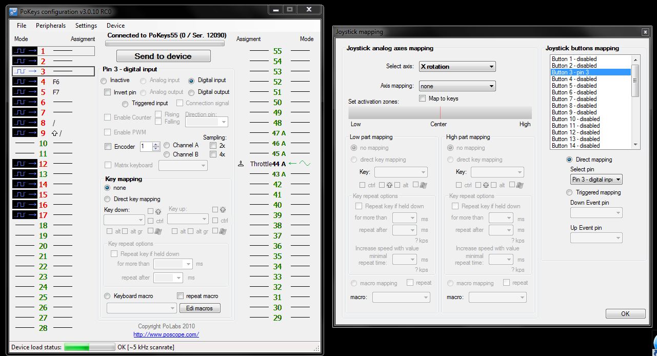
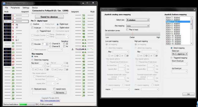
OK - sorted. As you suggested it was a configuration issue. It is necessary not only to configure the port on the card as a digital input but then to also map the port to a joystick button using the peripherals / joystick menu. I have attached an image in case it is of use to anyone else. Thank you for pointing me in the right direction.
-
I am using FSX and FSUIPC 4.728 I have attached the HID Scanner log below. I should correct what I said earlier. I have a simple throttle connected to one of the analogue inputs on the card which can be calibrated in FSUIPC and works in FSX. I have a couple of inputs set using the POKeys software to emulate F6 & F5 which are seen as a keypress by FSUIPC and work in FSX. I have a switch connected to the card to operate the parking brake which is seen by ProSim 737, operates the parking brake on the default 737-800 when ProSim is running but is not seen as a button press by either the windows game controller setup or FSUIPC. It does not operate the parking brake in FSX if ProSim is not running. I should say that I have just started experimenting with this card as it is relatively inexpensive and seems to have a lot of features. I cannot claim to understand 100% exactly what it is doing but I notice that in the log file one of the two entries for the card describes it as a 'virtual keyboard'. Thank you. ********* HidScanner, Version 2.00 by Pete Dowson ********* Device at "\\?\hid#vid_044f&pid_b108#8&368b84a9&0&0000#{4d1e55b2-f16f-11cf-88cb-001111000030}" Vendor=044F, Product=B108 (Version 1.0) Manufacturer= Thrustmaster Product= T.Flight Hotas X Serial Number= Usage Page: 1 Input Report Byte Length: 23 Output Report Byte Length: 3 Feature Report Byte Length: 13 Number of Link Collection Nodes: 1 Number of Input Button Caps: 1 Number of InputValue Caps: 18 Number of InputData Indices: 30 Number of Output Button Caps: 0 Number of Output Value Caps: 1 Number of Output Data Indices: 1 Number of Feature Button Caps: 0 Number of Feature Value Caps: 3 Number of Feature Data Indices: 3 Buttons range 1 -> 12 at indices 0 -> 11 Value POV at index 12, range 0 -> 7, using 4 bits Value X at index 13, range 0 -> 1023, using 10 bits Value Y at index 14, range 0 -> 1023, using 10 bits Value Sldr at index 15, range 0 -> 255, using 8 bits Value R/RZ at index 16, range 0 -> 255, using 8 bits Value Z at index 17, range 0 -> 255, using 8 bits Value 0x2B at index 18, range 0 -> 255, using 8 bits Value 0x2A at index 19, range 0 -> 255, using 8 bits Value 0x29 at index 20, range 0 -> 255, using 8 bits Value 0x28 at index 21, range 0 -> 255, using 8 bits Value 0x27 at index 22, range 0 -> 255, using 8 bits Value 0x26 at index 23, range 0 -> 255, using 8 bits Value 0x25 at index 24, range 0 -> 255, using 8 bits Value 0x24 at index 25, range 0 -> 255, using 8 bits Value 0x23 at index 26, range 0 -> 255, using 8 bits Value 0x22 at index 27, range 0 -> 255, using 8 bits Value 0x21 at index 28, range 0 -> 255, using 8 bits Value 0x20 at index 29, range 0 -> 255, using 8 bits ************************************************************************** Device at "\\?\hid#vid_045e&pid_00f9&mi_00#a&32dd356b&0&0000#{4d1e55b2-f16f-11cf-88cb-001111000030}" Vendor=045E, Product=00F9 (Version 0.3) Manufacturer= Microsft Product= Microsoft Wireless Desktop Receiver 3.1 Serial Number= Microsoft Wireless Desktop Receiver 3.1 Device is a keyboard Usage Page: 1 Input Report Byte Length: 9 Output Report Byte Length: 2 Feature Report Byte Length: 0 Number of Link Collection Nodes: 1 Number of Input Button Caps: 2 Number of InputValue Caps: 0 Number of InputData Indices: 154 Number of Output Button Caps: 2 Number of Output Value Caps: 0 Number of Output Data Indices: 4 Number of Feature Button Caps: 0 Number of Feature Value Caps: 0 Number of Feature Data Indices: 0 ************************************************************************** Device at "\\?\hid#vid_045e&pid_00f9&mi_01&col01#a&1fad192d&0&0000#{4d1e55b2-f16f-11cf-88cb-001111000030}" Vendor=045E, Product=00F9 (Version 0.3) Manufacturer= Microsft Product= Microsoft Wireless Desktop Receiver 3.1 Serial Number= Microsoft Wireless Desktop Receiver 3.1 Usage Page: C Input Report Byte Length: 4 Output Report Byte Length: 0 Feature Report Byte Length: 2 Number of Link Collection Nodes: 2 Number of Input Button Caps: 3 Number of InputValue Caps: 4 Number of InputData Indices: 7 Number of Output Button Caps: 0 Number of Output Value Caps: 0 Number of Output Data Indices: 0 Number of Feature Button Caps: 1 Number of Feature Value Caps: 2 Number of Feature Data Indices: 3 Value Wh at index 0, range -127 -> 127, using 8 bits Value 0x01 at index 1, range 0 -> 3, using 2 bits Value 0x03 at index 4, range 0 -> 3, using 2 bits Value 0x0D at index 6, range 0 -> 65535, using 16 bits ************************************************************************** Device at "\\?\hid#vid_045e&pid_00f9&mi_01&col02#a&1fad192d&0&0001#{4d1e55b2-f16f-11cf-88cb-001111000030}" Vendor=045E, Product=00F9 (Version 0.3) Manufacturer= Microsft Product= Microsoft Wireless Desktop Receiver 3.1 Serial Number= Microsoft Wireless Desktop Receiver 3.1 Device is a mouse Usage Page: 1 Input Report Byte Length: 6 Output Report Byte Length: 0 Feature Report Byte Length: 2 Number of Link Collection Nodes: 5 Number of Input Button Caps: 1 Number of InputValue Caps: 4 Number of InputData Indices: 9 Number of Output Button Caps: 0 Number of Output Value Caps: 0 Number of Output Data Indices: 0 Number of Feature Button Caps: 0 Number of Feature Value Caps: 2 Number of Feature Data Indices: 2 Buttons range 1 -> 5 at indices 0 -> 4 Value Y at index 5, range -127 -> 127, using 8 bits Value X at index 6, range -127 -> 127, using 8 bits Value Wh at index 7, range -127 -> 127, using 8 bits Value Wh at index 8, range -127 -> 127, using 8 bits ************************************************************************** Device at "\\?\hid#vid_045e&pid_00f9&mi_01&col03#a&1fad192d&0&0002#{4d1e55b2-f16f-11cf-88cb-001111000030}" Vendor=045E, Product=00F9 (Version 0.3) Manufacturer= Microsft Product= Microsoft Wireless Desktop Receiver 3.1 Serial Number= Microsoft Wireless Desktop Receiver 3.1 Usage Page: C Input Report Byte Length: 8 Output Report Byte Length: 0 Feature Report Byte Length: 2 Number of Link Collection Nodes: 4 Number of Input Button Caps: 8 Number of InputValue Caps: 9 Number of InputData Indices: 1549 Number of Output Button Caps: 0 Number of Output Value Caps: 0 Number of Output Data Indices: 0 Number of Feature Button Caps: 0 Number of Feature Value Caps: 2 Number of Feature Data Indices: 2 Value 0x0E at index 1280, range 0 -> 255, using 8 bits Value 0x05 at index 1283, range 0 -> 31, using 5 bits Value 0x02 at index 1539, range 1 -> 255, using 8 bits Value Wh at index 1540, range -127 -> 127, using 8 bits Value Wh at index 1541, range -127 -> 127, using 8 bits Value 0x02 at index 1542, range 0 -> 255, using 8 bits Value 0x01 at index 1543, range 0 -> 3, using 2 bits Value 0x03 at index 1546, range 0 -> 3, using 2 bits Value 0x0D at index 1548, range 0 -> 65535, using 16 bits ************************************************************************** Device at "\\?\hid#vid_045e&pid_00f9&mi_01&col04#a&1fad192d&0&0003#{4d1e55b2-f16f-11cf-88cb-001111000030}" Vendor=045E, Product=00F9 (Version 0.3) Manufacturer= Microsft Product= Microsoft Wireless Desktop Receiver 3.1 Serial Number= Microsoft Wireless Desktop Receiver 3.1 Usage Page: 1 Input Report Byte Length: 2 Output Report Byte Length: 0 Feature Report Byte Length: 0 Number of Link Collection Nodes: 1 Number of Input Button Caps: 1 Number of InputValue Caps: 0 Number of InputData Indices: 256 Number of Output Button Caps: 0 Number of Output Value Caps: 0 Number of Output Data Indices: 0 Number of Feature Button Caps: 0 Number of Feature Value Caps: 0 Number of Feature Data Indices: 0 ************************************************************************** Device at "\\?\hid#vid_06c2&pid_004c#9&1205cc9c&0&0000#{4d1e55b2-f16f-11cf-88cb-001111000030}" Vendor=06C2, Product=004C (Version 1.0) Manufacturer= Phidgets Inc. Product= PhidgetLED Serial Number= 114517 Usage Page: FFA0 Input Report Byte Length: 42 Output Report Byte Length: 9 Feature Report Byte Length: 0 Number of Link Collection Nodes: 1 Number of Input Button Caps: 0 Number of InputValue Caps: 1 Number of InputData Indices: 1 Number of Output Button Caps: 0 Number of Output Value Caps: 1 Number of Output Data Indices: 1 Number of Feature Button Caps: 0 Number of Feature Value Caps: 0 Number of Feature Data Indices: 0 Value 0x02 at index 0, range 0 -> 1, using 8 bits ************************************************************************** Device at "\\?\hid#vid_1dc3&pid_1001&mi_00#a&11f44069&0&0000#{4d1e55b2-f16f-11cf-88cb-001111000030}" Vendor=1DC3, Product=1001 (Version 16.0) Manufacturer= PoLabs Product= Virtual Joystick Serial Number= 1.12090 Usage Page: 1 Input Report Byte Length: 17 Output Report Byte Length: 0 Feature Report Byte Length: 0 Number of Link Collection Nodes: 2 Number of Input Button Caps: 1 Number of InputValue Caps: 6 Number of InputData Indices: 38 Number of Output Button Caps: 0 Number of Output Value Caps: 0 Number of Output Data Indices: 0 Number of Feature Button Caps: 0 Number of Feature Value Caps: 0 Number of Feature Data Indices: 0 Buttons range 1 -> 32 at indices 6 -> 37 Value U/RX at index 0, range 0 -> 1023, using 16 bits Value V/RY at index 1, range 0 -> 1023, using 16 bits Value Z at index 2, range 0 -> 1023, using 16 bits Value Y at index 3, range 0 -> 1023, using 16 bits Value X at index 4, range 0 -> 1023, using 16 bits Value Thr at index 5, range 0 -> 1023, using 16 bits ************************************************************************** Device at "\\?\hid#vid_1dc3&pid_1001&mi_01#a&29b7ccae&0&0000#{4d1e55b2-f16f-11cf-88cb-001111000030}" Vendor=1DC3, Product=1001 (Version 16.0) Manufacturer= PoLabs Product= Communication Interface Serial Number= 1.12090 Usage Page: FF00 Input Report Byte Length: 65 Output Report Byte Length: 65 Feature Report Byte Length: 0 Number of Link Collection Nodes: 1 Number of Input Button Caps: 0 Number of InputValue Caps: 1 Number of InputData Indices: 1 Number of Output Button Caps: 0 Number of Output Value Caps: 1 Number of Output Data Indices: 8 Number of Feature Button Caps: 0 Number of Feature Value Caps: 0 Number of Feature Data Indices: 0 Value 0x01 at index 0, range 0 -> 255, using 8 bits ************************************************************************** Device at "\\?\hid#vid_1dc3&pid_1001&mi_02#a&5e08eec&0&0000#{4d1e55b2-f16f-11cf-88cb-001111000030}" Vendor=1DC3, Product=1001 (Version 16.0) Manufacturer= PoLabs Product= Virtual keyboard Serial Number= 1.12090 Device is a keyboard Usage Page: 1 Input Report Byte Length: 35 Output Report Byte Length: 0 Feature Report Byte Length: 0 Number of Link Collection Nodes: 1 Number of Input Button Caps: 2 Number of InputValue Caps: 0 Number of InputData Indices: 110 Number of Output Button Caps: 0 Number of Output Value Caps: 0 Number of Output Data Indices: 0 Number of Feature Button Caps: 0 Number of Feature Value Caps: 0 Number of Feature Data Indices: 0 ************************************************************************** Device at "\\?\hid#vid_1dd2&pid_1001#8&276e438c&0&0000#{4d1e55b2-f16f-11cf-88cb-001111000030}" Vendor=1DD2, Product=1001 (Version 1.35) Manufacturer= Leo Bodnar Product= BU0836X Interface Serial Number= B07471 Usage Page: 1 Input Report Byte Length: 6 Output Report Byte Length: 0 Feature Report Byte Length: 18 Number of Link Collection Nodes: 3 Number of Input Button Caps: 1 Number of InputValue Caps: 1 Number of InputData Indices: 33 Number of Output Button Caps: 0 Number of Output Value Caps: 0 Number of Output Data Indices: 0 Number of Feature Button Caps: 0 Number of Feature Value Caps: 1 Number of Feature Data Indices: 1 Buttons range 1 -> 32 at indices 0 -> 31 Value POV at index 32, range 0 -> 7, using 4 bits ************************************************************************** Device at "\\?\hid#vid_1dd2&pid_1001#8&3288478d&0&0000#{4d1e55b2-f16f-11cf-88cb-001111000030}" Vendor=1DD2, Product=1001 (Version 1.33) Manufacturer= Leo Bodnar Product= BU0836X Interface Serial Number= B07138 Usage Page: 1 Input Report Byte Length: 6 Output Report Byte Length: 0 Feature Report Byte Length: 18 Number of Link Collection Nodes: 3 Number of Input Button Caps: 1 Number of InputValue Caps: 1 Number of InputData Indices: 33 Number of Output Button Caps: 0 Number of Output Value Caps: 0 Number of Output Data Indices: 0 Number of Feature Button Caps: 0 Number of Feature Value Caps: 1 Number of Feature Data Indices: 1 Buttons range 1 -> 32 at indices 0 -> 31 Value POV at index 32, range 0 -> 7, using 4 bits ************************************************************************** Device at "\\?\hid#vid_1dd2&pid_1001#9&11bc8276&0&0000#{4d1e55b2-f16f-11cf-88cb-001111000030}" Vendor=1DD2, Product=1001 (Version 1.35) Manufacturer= Leo Bodnar Product= BU0836X Interface Serial Number= B20384 Usage Page: 1 Input Report Byte Length: 6 Output Report Byte Length: 0 Feature Report Byte Length: 18 Number of Link Collection Nodes: 3 Number of Input Button Caps: 1 Number of InputValue Caps: 1 Number of InputData Indices: 33 Number of Output Button Caps: 0 Number of Output Value Caps: 0 Number of Output Data Indices: 0 Number of Feature Button Caps: 0 Number of Feature Value Caps: 1 Number of Feature Data Indices: 1 Buttons range 1 -> 32 at indices 0 -> 31 Value POV at index 32, range 0 -> 7, using 4 bits ************************************************************************** Device at "\\?\hid#vid_1dd2&pid_1001#9&3427402a&0&0000#{4d1e55b2-f16f-11cf-88cb-001111000030}" Vendor=1DD2, Product=1001 (Version 1.35) Manufacturer= Leo Bodnar Product= BU0836X Interface Serial Number= B18398 Usage Page: 1 Input Report Byte Length: 6 Output Report Byte Length: 0 Feature Report Byte Length: 18 Number of Link Collection Nodes: 3 Number of Input Button Caps: 1 Number of InputValue Caps: 1 Number of InputData Indices: 33 Number of Output Button Caps: 0 Number of Output Value Caps: 0 Number of Output Data Indices: 0 Number of Feature Button Caps: 0 Number of Feature Value Caps: 1 Number of Feature Data Indices: 1 Buttons range 1 -> 32 at indices 0 -> 31 Value POV at index 32, range 0 -> 7, using 4 bits **************************************************************************
-
Has anyone tried using one of these: http://www.flightsimparts.eu/Shop_Electronics_Pokeys55.html with FSUIPC. It is seen by Windows as a 'virtual joystick' and is listed with a GUID (and assigned a letter) in my FSUIPC.INI file. Switches attached to the card are recognised in ProSim and Windows game controller setup but I cannot get any response to a button click (or keypress)in the FSUIPC interface. Buttons connected to a BU0386X card are detected perfectly by FSUIPC. Thank you.
-
Blimey Pete - you must be mellowing. When I read that post I was expecting fireworks. Regards, Philip :lol:
-
I have read the post explaining bits, numbers and hexadecimal and have a (very) basic question. If you take the offset for Autopilot altitude lock (07D0) it is documented as 4 bytes (and is therefore a DWORD?). As far as I can gather the offset on holds two values: 0 for off and 1 for on so why does it need 4 bytes or 32 bits to accomplish this. A link to further reading on this subject would be most welcome. Thank you, Philip
-
Yes - I see what you mean - daft question with hindsight, it all seems so obvious now. Kind regards, Philip
-
Dear Pete, If I have a momentary switch (pushbutton) and press it the button flag changes from 0 to 1. Does it change back to 0 the next time the button is pressed or on the release of the first press? Thank you, Philip
-
Real Air Marchetti SF260 Autopilot
flatdog replied to flatdog's topic in FSUIPC Support Pete Dowson Modules
Cracked it: if ipcPARAM == 4 then i = ipc.readLvar("L:AP_ALT_HOLD_VAR") ipc.writeLvar("L:AP_ALT_HOLD_VAR", i+1000) end if ipcPARAM == 5 then i = ipc.readLvar("L:AP_ALT_HOLD_VAR") ipc.writeLvar("L:AP_ALT_HOLD_VAR", i-1000) end if ipcPARAM == 6 then i = ipc.readLvar("L:AP_ALT_HOLD_VAR") ipc.writeLvar("L:AP_ALT_HOLD_VAR", i+100) end if ipcPARAM == 7 then i = ipc.readLvar("L:AP_ALT_HOLD_VAR") ipc.writeLvar("L:AP_ALT_HOLD_VAR", i-100) end I had missed out the "." in ipc.readLvar - tired eyes I guess. This needs more work because the AP should only go to 9000 ft and then return to 0 - but it works and I have learned a lot in the process. Thanks, Philip -
Real Air Marchetti SF260 Autopilot
flatdog replied to flatdog's topic in FSUIPC Support Pete Dowson Modules
The correct control is AP_ALT_HOLD_VAR So with ipc.writeLvar("L:AP_ALT_HOLD_VAR", 1000) the button now changes the display to 1000. I now want to read the current value and increase it by 1000 so I have (in my SF160.lua file): if ipcPARAM == 3 then i = ipcreadLvar("L:AP_ALT_HOLD_VAR") ipc.writeLvar("L:AP_ALT_HOLD_VAR", i+1000) end alas this does not yet work but at least I am on the right track. The error is: ********* LUA: "SF160" Log [from FSUIPC version 4.623] ********* 5131590 System time = 11/09/2010 19:18:50, Simulator time = 17:57:15 (00:57Z) 5131590 LUA: beginning "C:\Program Files (x86)\Microsoft Games\Microsoft Flight Simulator X\Modules\SF160.lua" 5131590 *** LUA Error: ...Games\Microsoft Flight Simulator X\Modules\SF160.lua:16: attempt to call global 'ipcreadLvar' (a nil value) 5131590 LUA: ended "C:\Program Files (x86)\Microsoft Games\Microsoft Flight Simulator X\Modules\SF160.lua" 5131590 System time = 11/09/2010 19:18:50, Simulator time = 17:57:15 (00:57Z) ********* LUA execution terminated: Log Closed ********* -
Real Air Marchetti SF260 Autopilot
flatdog replied to flatdog's topic in FSUIPC Support Pete Dowson Modules
OK so when I use the rotary encoder set up for the com radio I get: 16316643 Button changed: bRef=0, Joy=1 (B), Btn=14, Pressed 16316643 [buttons.SIAI-Marchetti SF.260 Left Gold] 40=CP(-B,8)B,14,C65637,0 16316643 .... Condition (-B,8) = TRUE 16316643 FS Control Sent: Ctrl=65637, Param=0 16316643 [buttons.SIAI-Marchetti SF.260 Left Gold] 45=CP(+B,8)B,14,C66437,0 16316643 .... Condition (+B,8) = FALSE 16316643 *** EVENT: Cntrl= 65637 (0x00010065), Param= 0 (0x00000000) COM_RADIO_WHOLE_INC .... and the digits on the screen change as expected. When I press the button set up to test the autopilot altitude knob I get: 16331651 Button changed: bRef=0, Joy=3 (D), Btn=0, Pressed 16331651 [buttons.SIAI-Marchetti SF.260 Left Gold] 123=PD,0,C66124,0 16331651 FS Control Sent: Ctrl=66124, Param=0 16331651 *** EVENT: Cntrl= 66124 (0x0001024c), Param= 0 (0x00000000) AP_ALT_VAR_SET_ENGLISH 16331822 Button changed: bRef=0, Joy=3 (D), Btn=0, Released ..... but the digits on screen (which I set to 1000 with the mouse before pressing the button) do not change. The log file looks OK .... I think? Regards, Philip -
Real Air Marchetti SF260 Autopilot
flatdog replied to flatdog's topic in FSUIPC Support Pete Dowson Modules
I have been on a bit of a wild goose chase with this. I started from scratch and used the various logging facilities again and found: 251177 *** EVENT: Cntrl= 66124 (0x0001024c), Param= 1000 (0x000003e8) AP_ALT_VAR_SET_ENGLISH 251177 *** EVENT: Cntrl= 66124 (0x0001024c), Param= 1000 (0x000003e8) AP_ALT_VAR_SET_ENGLISH 251239 *** EVENT: Cntrl= 66124 (0x0001024c), Param= 1000 (0x000003e8) AP_ALT_VAR_SET_ENGLISH 251239 *** EVENT: Cntrl= 66124 (0x0001024c), Param= 1000 (0x000003e8) AP_ALT_VAR_SET_ENGLISH 251302 *** EVENT: Cntrl= 66124 (0x0001024c), Param= 2000 (0x000007d0) AP_ALT_VAR_SET_ENGLISH 251364 *** EVENT: Cntrl= 66124 (0x0001024c), Param= 2000 (0x000007d0) AP_ALT_VAR_SET_ENGLISH 251426 *** EVENT: Cntrl= 66124 (0x0001024c), Param= 2000 (0x000007d0) AP_ALT_VAR_SET_ENGLISH 251489 *** EVENT: Cntrl= 66124 (0x0001024c), Param= 2000 (0x000007d0) AP_ALT_VAR_SET_ENGLISH I have assigned a button to AP_ALT_VAR_SET_ENGLISH with a parameter of 0. I had hoped that if I dialled in an altitude of say 2000 with the mouse and then pressed the button the altitude should be set to 0 but nothing happens. The log shows: ********* FSUIPC4, Version 4.623 by Pete Dowson ********* User Name="Philip Roberts" User Addr="pRoberts@nf-castings.co.uk" FSUIPC4 Key is provided WIDEFS7 not user registered, or expired [Continuation log requested by user] Running inside FSX on Windows Vista (using SimConnect Acc/SP2 Oct07) Module base=61000000 Wind smoothing fix is fully installed (Non relevant lines omitted) ....... 929407 [buttons.SIAI-Marchetti SF.260 Left Gold] 123=PD,0,C66124,0 929407 FS Control Sent: Ctrl=66124, Param=0 929641 Button changed: bRef=0, Joy=3 (D), Btn=0, Released I have also tried setting the parameter to 3000 but still no luck. -
Real Air Marchetti SF260 Autopilot
flatdog replied to flatdog's topic in FSUIPC Support Pete Dowson Modules
The dual concentric knob 'on-screen' is operated by left dragging up and down with the mouse on the outer ring to increase / decrease 1000's and right dragging up and down on the inner ring to +/- 100's. There are quite a few instances of apAltDrag and apAltDragStep in the log file all with different values, I just included those two as an example. I perhaps naively assumed that they referred to autopilot altitude and a mouse drag. I had been dragging the knobs up & down while logging to try to find out what was happening but the values on screen were scrolling so fast that I couldn't be 100% sure what was happening. I had hoped that if I could get a button to set a value of 100 I would at least know that was on the right track. -
Real Air Marchetti SF260 Autopilot
flatdog replied to flatdog's topic in FSUIPC Support Pete Dowson Modules
I have been going through the Lvars.log file again and have found: 302752 LUA: L:apAltDragStep=659 302798 LUA: L:apAltDrag=653 Assuming that these are correct and to keep things simple I would like to create two standalone .lua files, one to increase / decrease in 100's and one in 1000's. I think that the format would be something like ipc.writeLvar("L:apAltDragStep", 100) but would be very happy to receive some guidance. I have tried putting this line into a file called apAltSlow.lua and assigned a button to it but am not having much success. Thanks, Philip