Sea2Sky
-
Posts
18 -
Joined
-
Last visited
Sea2Sky's Achievements
")


-
Unable to Manually Edit & Save FSUIPC6.ini
Sea2Sky replied to Sea2Sky's topic in FSUIPC Support Pete Dowson Modules
I should have known better, I have all the documentation spiral bound. Thanks for letting me know. Keep up the great work! -
Unable to Manually Edit & Save FSUIPC6.ini
Sea2Sky replied to Sea2Sky's topic in FSUIPC Support Pete Dowson Modules
Hey John, thanks for the speedy reply. The idea was not have to update the ini file manually, but to back it up and have the ability to restore FSUIPC6 without the need of re-configuring the buttons in the FSUIPC application. I've done this in the past; this time around my backed up copy of the INI file restored all buttons except for a few rotary knobs. I've decided to use the FSUIPC application to reprogram the rotary dials and have backed up my recent changes. After making the necessary adjustments, I see that K# value is what appears to maps the keys. I was initially looking for documentation on FSUIPC6.ini key/values, but I don't think it's publicly available. I've been trying to decode the values using common sense with some process of elimination. I understand that the 'A' and 'C' in PA, and PC map to the JoyNames. Still trying to determine what the P and R represent; initially I thought it was Push vs Rotary. In response to 'Why am I updating your INI manually?'. My career is in systems engineering so I prefer working on text configurations for any quick changes utilizing the key/value pair data. I misunderstood the INI functionality and didn't realize that the -{Key press: }- portion was a comment, thank you far clarifying. -
I've performed a clean install of my OS and Flight Simulation applications and the last task I need to complete is configuring my GNS 530 GPS device with FSUIPC. I've backed up a copy of my FSUIPC6.ini file for my GNS 530 that's running Reality XP as well as the RXP config. This maps RXP keys to the button keys in FSUIPC6.ini. The issue I'm having which is a new one for me over the years with FSUIPC6 is that I need to update a few FSUIPC6.ini button entries to match my RXP configured keys. After I save my FSUIPC6.ini file (and confirm it's been saved by reopening it with the latest changes), I then start up P3D v5.3. When P3D v5.3 loads up, it reverts all my changes to what was in the FSUIPC6.ini file from before. I'm not sure how FSUIPC6 is performing the config reverts and was hoping that someone could shed some light as to what's happening to my FSUIPC6.ini file when P3Dv5 starts. Is there some sort of cached options stores somewhere, or something else I'm missing? I don't recall this being an issue in the past when manually editing changes in the FSUIPC6.ini file. I've included a copy of the JoyNames and Buttons section from both the in-game FSUIPC6.ini options as well as the options I've been trying to save. Let me know if there are other details needed from me or my FSUIPC configs. These are the FSUIPC button settings I want configured, and have copied over to my in-game FSUIPC6.ini file. [JoyNames] AutoAssignLetters=Yes A=CLSE NG Yoke A.GUID={CCDFAA90-9026-11EC-8002-444553540000} B=JAY Rudder B.GUID={CCDFAA90-9026-11EC-8004-444553540000} C=GarSim 530 C.GUID={CCDFAA90-9026-11EC-8005-444553540000} 0=CLSE NG Yoke 0.GUID={CCDFAA90-9026-11EC-8002-444553540000} 1=JAY Rudder 1.GUID={CCDFAA90-9026-11EC-8004-444553540000} 2=GarSim 530 2.GUID={CCDFAA90-9026-11EC-8005-444553540000} [Buttons] PollInterval=25 ButtonRepeat=20,10 1=PA,0,C65561,0 -{PAUSE_TOGGLE}- 2=PA,1,C66653,0 -{VIEW_COCKPIT_FORWARD}- 3=PA,2,C66654,0 -{VIEW_VIRTUAL_COCKPIT_FORWARD}- 4=PA,4,C65906,0 -{PANEL_1}- 5=PA,3,C66482,0 -{TOGGLE_WATER_RUDDER}- 6=PA,5,C65567,0 -{VIEW_MODE}- 7=PC,12,K112,11 -{Key press: ctl+shft+F1}- 8=PC,0,K69,11 -{Key press: ctl+shft+E}- 9=PC,13,K113,11 -{Key press: ctl+shft+F2}- 10=PC,7,K74,11 -{Key press: ctl+shft+I}- 11=PC,6,K73,11 -{Key press: ctl+shft+J}- 12=PC,5,K76,11 -{Key press: ctl+shft+O}- 13=PC,4,K85,11 -{Key press: ctl+shft+N}- 14=PC,14,K78,40 -{Key press: win+N}- 15=PC,16,K114,11 -{Key press: ctl+shft+F3}- 16=PC,17,K115,11 -{Key press: ctl+shft+F4}- 17=PC,18,K116,11 -{Key press: ctl+shft+F5}- 18=PC,19,K117,11 -{Key press: ctl+shft+F6}- 19=PC,20,K118,11 -{Key press: ctl+shft+F7}- 20=PC,21,K119,11 -{Key press: ctl+shft+F8}- 21=PC,10,K87,11 -{Key press: ctl+shft+L}- 22=PC,11,K86,11 -{Key press: ctl+shft+K}- 23=PC,8,K89,11 -{Key press: ctl+shft+P}- 24=PC,9,K88,11 -{Key press: ctl+shft+Q}- 25=PC,15,K77,11 -{Key press: ctl+shft+M}- 26=RC,27,K66,11 -{Key press: ctl+shft+B}- 27=RC,26,K65,11 -{Key press: ctl+shft+A}- 28=PC,25,K123,11 -{Key press: ctl+shft+F12}- 29=PC,24,K122,11 -{Key press: ctl+shft+F11}- 30=RC,23,K121,11 -{Key press: ctl+shft+F10}- 31=PC,22,K120,11 -{Key press: ctl+shft+F9}- 32=PC,29,K67,11 -{Key press: ctl+shft+.}- 33=PC,28,K117,11 -{Key press: ctl+shft+,}- 34=PC,1,K68,11 -{Key press: ctl+shft+D}- 35=PC,3,K71,11 -{Key press: ctl+shft+G}- 36=PC,2,K72,11 -{Key press: ctl+shft+H}- These are the settings FSUIPC keeps reverting to when starting P3Dv5. [JoyNames] AutoAssignLetters=Yes A=CLSE NG Yoke A.GUID={CCDFAA90-9026-11EC-8002-444553540000} B=JAY Rudder B.GUID={CCDFAA90-9026-11EC-8004-444553540000} C=GarSim 530 C.GUID={CCDFAA90-9026-11EC-8005-444553540000} 0=CLSE NG Yoke 0.GUID={CCDFAA90-9026-11EC-8002-444553540000} 1=JAY Rudder 1.GUID={CCDFAA90-9026-11EC-8004-444553540000} 2=GarSim 530 2.GUID={CCDFAA90-9026-11EC-8005-444553540000} [Buttons] PollInterval=25 ButtonRepeat=20,10 1=PA,0,C65561,0 -{PAUSE_TOGGLE}- 2=PA,1,C66653,0 -{VIEW_COCKPIT_FORWARD}- 3=PA,2,C66654,0 -{VIEW_VIRTUAL_COCKPIT_FORWARD}- 4=PA,4,C65906,0 -{PANEL_1}- 5=PA,3,C66482,0 -{TOGGLE_WATER_RUDDER}- 6=PA,5,C65567,0 -{VIEW_MODE}- 7=PC,12,K112,11 -{Key press: ctl+shft+F1}- 8=PC,0,K69,11 -{Key press: ctl+shft+E}- 9=PC,13,K113,11 -{Key press: ctl+shft+F2}- 10=PC,7,K74,11 -{Key press: ctl+shft+J}- 11=PC,6,K73,11 -{Key press: ctl+shft+I}- 12=PC,5,K76,11 -{Key press: ctl+shft+L}- 13=PC,4,K85,11 -{Key press: ctl+shft+U}- 14=PC,14,K78,40 -{Key press: win+N}- 15=PC,16,K114,11 -{Key press: ctl+shft+F3}- 16=PC,17,K115,11 -{Key press: ctl+shft+F4}- 17=PC,18,K116,11 -{Key press: ctl+shft+F5}- 18=PC,19,K117,11 -{Key press: ctl+shft+F6}- 19=PC,20,K118,11 -{Key press: ctl+shft+F7}- 20=PC,21,K119,11 -{Key press: ctl+shft+F8}- 21=PC,10,K87,11 -{Key press: ctl+shft+W}- 22=PC,11,K86,11 -{Key press: ctl+shft+V}- 23=PC,8,K89,11 -{Key press: ctl+shft+Y}- 24=PC,9,K88,11 -{Key press: ctl+shft+X}- 25=PC,15,K77,11 -{Key press: ctl+shft+M}- 26=RC,27,K66,11 -{Key press: ctl+shft+B}- 27=RC,26,K65,11 -{Key press: ctl+shft+A}- 28=PC,25,K123,11 -{Key press: ctl+shft+F12}- 29=PC,24,K122,11 -{Key press: ctl+shft+F11}- 30=RC,23,K121,11 -{Key press: ctl+shft+F10}- 31=PC,22,K120,11 -{Key press: ctl+shft+F9}- 32=PC,29,K67,11 -{Key press: ctl+shft+C}- 33=PC,28,K117,11 -{Key press: ctl+shft+F6}- 34=PC,1,K68,11 -{Key press: ctl+shft+D}- 35=PC,3,K71,11 -{Key press: ctl+shft+G}- 36=PC,2,K72,11 -{Key press: ctl+shft+H}-
-
FSUIPC6 Addon Option goes to Black Screen for P3D v5
Sea2Sky replied to Sea2Sky's topic in FSUIPC Support Pete Dowson Modules
Hey John, Thanks for the advice. It was indeed the OptionsDialogOffset that stored my old display data, therefore preventing the FSUIPC popup to appear on screen. "I can't do anything by ALT-F4" > Typo, should have read "anything but ALT-4". Good tip on InvokeFSUIPCOptionsKey , as I haven't set up the FSUIPC shortcut key. Keep up the good work! -
I've been a long time user of FSUIPC4, 5 and 6. I have FSUIPC6 on P3D v5, and the button configurations are still working. However, lately when I go to the Addons > FSUIPC6 menu, it goes to a black screen and I can't do anything by ALT-F4, which gives me the P3D exit popup. The only notable changes I have made was that I installed FSUIPC7 for MSFS2020 (I would also FSUIPC7 wouldn't have any issues with FSUIPC6 installed) and have rearranged monitors and resolution rate. Is there a configuration parameter in where the FSUIPC addon panel loads up at a certain screen x,y location? Any help to troubleshoot what is happening here would be greatly appreciated, thank you.
-
Searching for specific FSUIPC5 offsets
Sea2Sky replied to Sea2Sky's topic in FSUIPC Support Pete Dowson Modules
I've resolved my issue, and wanted to post the solution here in case anyone in the future is searching for a similar answer. The bit mask was on the bottom right corner 'Mask if Bit cmd'. In the past, I was using the bit flag values of 0-9, rather than the bit values of 1, 2, 4, 8, 16, 32, 64, 128, 256, and 512. If anyone has this issue, I hope that this can help. Much thanks to the FSUIPC team for dealing with me, and for clearing up any misunderstandings I had with the offset hex values.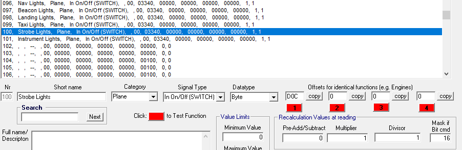
-
Searching for specific FSUIPC5 offsets
Sea2Sky replied to Sea2Sky's topic in FSUIPC Support Pete Dowson Modules
Thank you, I will start troubleshooting more with the FSUIPC logging facilities in the future. Yes, that was the case. I would hope that there is a way somewhere to configure this bit, and I will continue to troubleshoot the software in question. Thank you, this makes total sense. My original assumption was that FSUIPC hex offsets were based on an adjustable programmatic FSUIPC value changing the bytes in the initial offset, not an additional byte/parameter set. Understanding that it's an actual byte in memory definitely clears things up for me. Due to the options presented to me in my hardware's software, I was making an incorrect guess and changing the initial offset value. I required a deeper understanding of FSUIPC. I will sit down and start reviewing the Lua code better understand how it's designed to work. Clearly my understanding was misunderstood. I will also make some time to sit down and read through all the FSUIPC manuals I have in front of me, rather than skimming to what I'm after. Thank you all for your time. I feel more at ease being educated on the subject, and knowing where to look next. -
Searching for specific FSUIPC5 offsets
Sea2Sky replied to Sea2Sky's topic in FSUIPC Support Pete Dowson Modules
I am so frustrated and disappointed in myself that I can't comprehend what is being said. I understand in theory what you mean, but not in practice. Unfortunately, when I set a particular bit in a byte, the offset value changes for me, and all I can do is enter an offset value to set the function within my software. If you only knew how many times I've read, and re-read that article. 😞 Once again, when I change any bit, the offset value changes for me, and that is the only thing I can enter in my software is an offset value. There are other data types I can change as well other than Bytes, which include Integer, Unsigned Integer, Long, Double, and BCD Code. As mentioned, 0000 1101 0000 0010 = 502 was the second bit, and did not work within the default Cessna 172 aircraft supplied by FSX. This did work when assigning a yoke button directly in FSUIPC as 'Offset Work Togglebits' FS control, so the switch does appear to work for that aircraft using that method only. I appreciate all your advice, and thank you for your support, but it doesn't appear that I can get it working after spending full days attempting this. Thank you so much for trying, but I am at a loss of what to do anymore. I can sense that some of you are as frustrated with me, as I am with setting the bits. So I think it is best for me to walk away as this has caused aggravating stress for both me and you. My current assumption is that the issue lies in the software I'm using for my hardware which only uses offset values to define the functions. I will reach out to them and see if that is the case. I will continue to support and praise your project, and was looking to donate for all your time, but I no longer see the donation contribution page. -
Searching for specific FSUIPC5 offsets
Sea2Sky replied to Sea2Sky's topic in FSUIPC Support Pete Dowson Modules
Thanks Thomas, So to my understanding, offset 0D0C are 2 bytes, (2x 8 bits) which is: 0000 1101 0000 1100 = 0D0C I've been tying to figure out which bit to flip within which byte in the 0D0C offset. I'll limit my example to just the beacon light. Here's the attempt flipping bit 1, by flipping the bit in the second bit, which changes the offset value to 502. As expected this doesn't work as the offset value has changed in only the second byte. 0000 1101 0000 0010 = 502 Attempting to change the beacon bit to the first byte also doesn't work, as expected, since the offset value changes: 0000 0010 0000 1100 = 20C So let's clear all the bits, and try the following which also does not work as expected because the 0D0C offset no longer exists: 0000 0000 0000 0010 = 2 No need in even attempting this, since the offset would be 2, which does not make sense, and would not apply to other offset function values that have bit flags. So then I thought, what if we make it 4 bytes, keep the 0D0C 2 byte offset, and then added 2 bytes previous to the offset which would look like this: 0000 0000 0000 0010 0000 1101 0000 1100 = 20D0C This seemed promising at first since the offset 0D0C remained, with an additional bit added. And attempted flipping another bit to test landing lights: 0000 0000 0000 0100 0000 1101 0000 1100 = 40D0C This unfortunately did not work as well. So I guess my question is, which bit am I flipping, while still keeping the 0D0C offset value? I'm guessing there is a bit outside of the offset that needs to be flipped that I'm not aware of to retain the 0D0C offset? Otherwise, I would assume my question would have been answered with a unique offset value per individual light. Is there a missing bit flag field within my G-Step configuration software that I pasted in an earlier post? Am I on the right path of flipping bits, but just not in the right byte? -
Searching for specific FSUIPC5 offsets
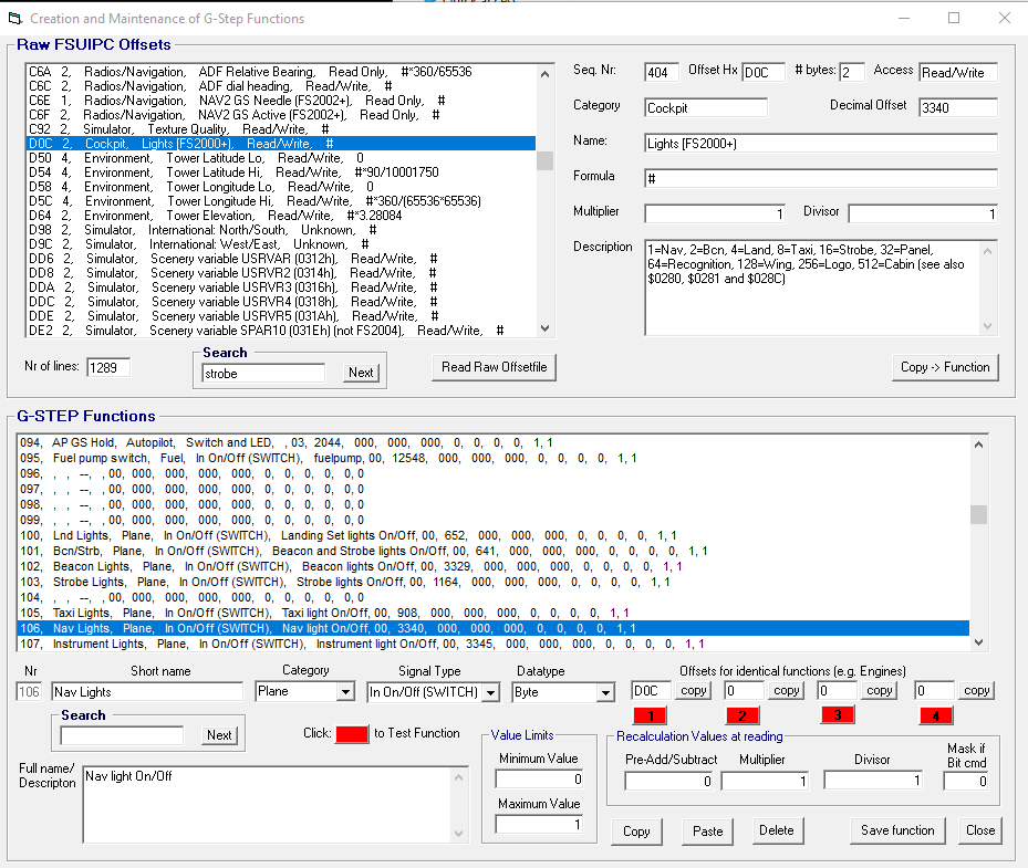
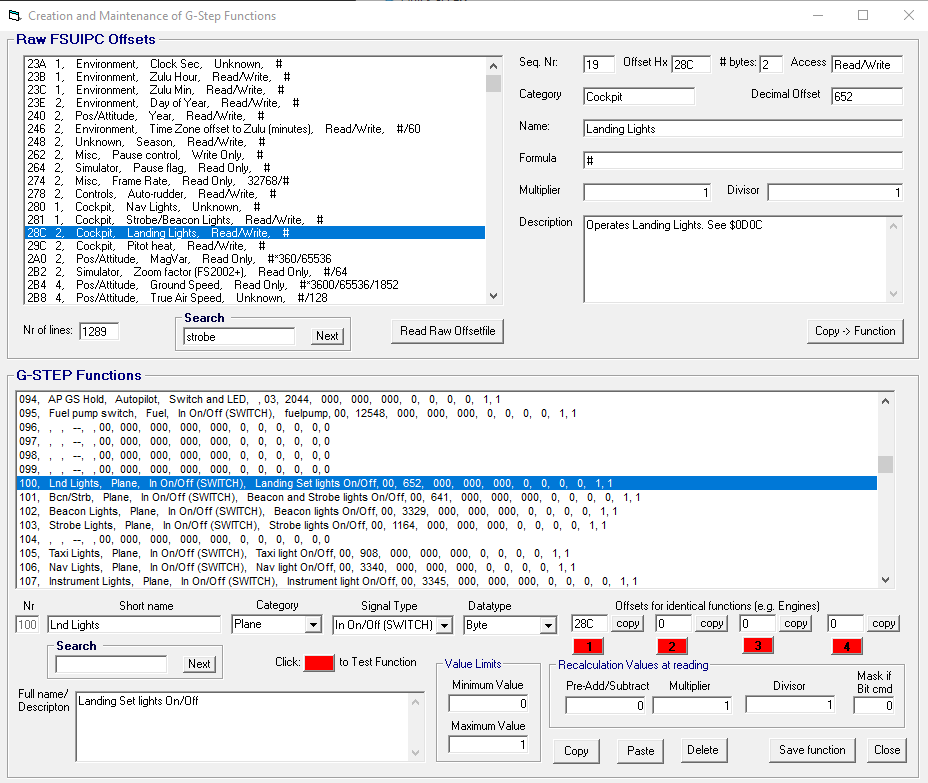
Sea2Sky replied to Sea2Sky's topic in FSUIPC Support Pete Dowson Modules
I found this to be completely helpful when assigning the FS control function parameter to a button on my yoke. Testing it allowed me to toggle each switch accordingly, and gives me much hope in finding a solution! I need to figure out if converting it to a new hex offset value is the right or wrong path. I'm using an IO board from Flight Illusion which has its own function configuration that maps to my switches, and I've been trying to figure out the offset conversions for each individual light. I've been trying to convert binary to hex by changing the bit values to calculate the offset value. My original assumption was that 0D0C was the main offset, and I had to replace the bits at the end, which was incorrect. To give you an example of what I'm working with, here is the NAV light function which is set to 0D0C. I've also noticed an offset of 280 which also appears to be used as NAV (NAV, Taxi, and Wing lights), but am currently using 0D0C, which converts to binary 1101 0000 1100: There is also an offset of 28C (binary: 0010 1000 1100) which also activates the Landing lights switch: So using the Nav and Landing lights function, I am seeing the following binary: Nav (280): 0010 1000 0000 Landing (28C): 0010 1000 1100 But don't understand how those are related to the binary offset of 0D0C (they might be completely unrelated): Nav (0D0C): 1101 0000 1100 I want to understand very badly what you two are saying, but maybe I'm approaching this completely wrong. I appear to be missing something in regards to converting the binary from the 0D0C offset value. Are there any other fields within the offsets function field that need to be updated shown above other than the offset field, or am I on the right track on assuming that the offset value is recalculated by changing bit values within the converted 0D0C hex to binary string? Unfortunately, the only working offset examples I have for the lights are 280, 28C, and 0D0C as listed in the offset guide. I'm starting to think that it's not the offset value that I need to change within the IO board software, but something else? Once again, apologies if there's any frustration on your part from something that I might be missing here. I'm trying really hard to understand what it is that I'm doing wrong as far as the offset hex conversion (if that's even the case). I might be trying to apply the offsets for beacon, taxi, strobe that might not even exist based on incorrect binary conversion? Or maybe the offset field is to remain as 0D0C, and there is another bit/flag elsewhere that needs to be added? I promise you, there is a dram of really fine scotch waiting for you in Canada if you can help me solve this. 🙂

-
I think you are correct and hit the nail on the head. In the end, I did remove all device button mapping for each device within P3D. But yesterday, I may have missed vJoy device in P3D. As of last night, all assignments were cleared up in P3D, and FSUIPC did use the correct device ID 1. Since everything is working now, I will walk away from this with hopes of it not reoccurring. Thank you for your help throughout my post ramblings. :-)
-
I guess my struggle is this: vJoy device 0 *is* device CLSE NG 1, and vice versa. The yoke can use both devices for button mapping in FSUIPC. When the yoke buttons work correctly, FSUIPC identifies the yoke buttons as device 1. When it does, all buttons are mapped to device 1, and the hat switch works accordingly. The buttons will use P1:0, P1:1, P1:2. When FSUIPC includes vJoy device 0 as part of the yoke button configuration, then I get a mishmash of yoke buttons using both joystick devices, and certain hat switch directions become device 0. Example: when FSUIPC loads the yoke buttons properly, only CLSE NG device 1 is used for all yoke button mappings, including the hat switch. But sometimes on load, FSUIPC uses both device IDs for button mapping, and then P0:5, P0:6, P0:7 overrides P1:0, P1:1, P1:2. I'm trying my best to identify the situation I'm seeing in FSUIPC, it would have been better to create a video to explain what I'm speaking about if the above doesn't make sense, which I would be willing to do if necessary. Next time this issue persists, I will try changing to Joy Letters to see if that resolves the issues. Thank you for your patience Pete, as this is a bit of an odd issue, and I don't think is normal. All USB inputs are set in a USB extender, and are never removed.
-
Searching for specific FSUIPC5 offsets
Sea2Sky replied to Sea2Sky's topic in FSUIPC Support Pete Dowson Modules
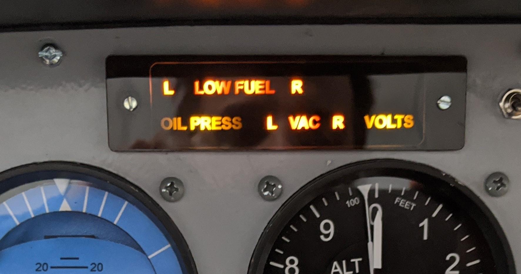
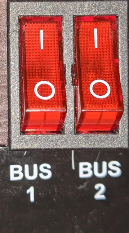
It was more related to the annunciator panel hardware that I'm trying to configure. It has warning indicator lights for L/R VAC, and I was trying to find the offset values for this in particular. Regarding the Avionics Bus1 and Bus2 switch, once again, this is hardware specific to my simulator. If there are no offsets for these, please let me know and I will move on and will ignore some of hardware limitations. Regarding the instrument light bits, I'm very well aware of what a bit is, but might not understand how they are used as flags if the following bits aren't working for individual Beacon, Landing, Taxi, and Strobe lights. Let's convert my hex example to binary to discuss what I mean: 0D0C: Nav = 1101 0000 1100 ***WORKING*** (reducing to 12 bit for simplicity, otherwise 0000 1101 0000 1100) 0D0D: Beacon = 1101 0000 1101 0D0E: Landing = 1101 0000 1110 0D0F: Taxi Lights = 1101 0000 1111 0D10: Strobe =1101 0001 0000 0D11: Instrument = 1101 0001 0001 ***WORKING*** I've flipped each bit, and Nav and Instrument light switch works according to the bits set above. According to the Offsets Guide, the bits go from 0 (Nav) to 9 (Cabin), in which in this case, I'm trying to make use of bits 0-5. If I've misunderstood flipping each bit in the offset between Nav and Instrument bits, please help me understand. Since Instrument lights do work with 0D0C + 5 bits = 0D11, and 0D0C = 0 bit switch, then why wouldn't 0D0C + 1 = 0D0D? If Beacon is not 0D0D, could you please give me a freebie on what the Beacon light offset is, so I can get a better grasp on what you're talking about.
-
I've tried to uninstall/reinstall my hardware control devices but kept running into joystick conflict issues. I replaced a lot of my Saitek controls with more professional simulation hardware, and after going over the controllers in the registry, and old driver removal, I eventually gave up. I did a fresh reinstall of Windows 10, P3D, hardware controls/drivers, scenery packages, and FSUIPC. I've cleared out all controls within P3D, and am exclusively using FSUIPC. I just finished setting up my hardware in FSUIPC, and everything is looking good (except the individual light switches, as mentioned in a separate post). One issue that I've noticed which seems to be random is in regards to my Brunner CLSE NG yoke. It has it's own software and support, but does require vJoy to also be installed. Sometimes FSUIPC recognizes half my buttons on the yoke to be from the vJoy device ID, and other times, it's recognized as the CLSE NG Yoke device ID. Is there any known conflicts with vJoy and CLSE NG devices, and how can I keep the buttons consistent to the appropriate ID. The best case working scenario for me is when all the yoke buttons are identified in FSUIPC as the CLSE NG device ID. I've attached a copy of my FSUIPC.JoyScan.csv file for reference: Good?, flags, VID, PID, Name, INIid, REGid, RegEntry, INIguid, REGguid, HIDguid, ValsOK?, ReadsOk? ,,, HIDscanning completed N, x00, x241D, xFE4E, , -1, -1, 0, {NULL}, {NULL}, {52571BC0-6B69-11EA-8005-444553540000}, Y, N N, x00, x1234, xBEAD, , -1, -1, 0, {NULL}, {NULL}, {0FB96D90-6B69-11EA-8002-444553540000}, Y, N N, x00, x1DD2, x1020, , -1, -1, 0, {NULL}, {NULL}, {DEC169D0-6B73-11EA-8002-444553540000}, Y, N N, x00, x25BB, x008B, , -1, -1, 0, {NULL}, {NULL}, {52560A50-6B69-11EA-8003-444553540000}, Y, N ,,, REGscanning completed N, x00, x241D, xFE4E, JAY Rudder, -1, 2, 0, {NULL}, {52571BC0-6B69-11EA-8005-444553540000}, {52571BC0-6B69-11EA-8005-444553540000}, Y, Y N, x00, x1234, xBEAD, vJoy Device, -1, 0, 0, {NULL}, {0FB96D90-6B69-11EA-8002-444553540000}, {0FB96D90-6B69-11EA-8002-444553540000}, Y, Y N, x00, x1DD2, x1020, GarSim 530, -1, 3, 0, {NULL}, {DEC169D0-6B73-11EA-8002-444553540000}, {DEC169D0-6B73-11EA-8002-444553540000}, Y, N N, x00, x25BB, x008B, CLSE NG Yoke, -1, 1, 0, {NULL}, {52560A50-6B69-11EA-8003-444553540000}, {52560A50-6B69-11EA-8003-444553540000}, Y, Y N, x00, x25BB, x008B, CLSE NG Yoke, -1, -1, 1, {NULL}, {52565870-6B69-11EA-8004-444553540000}, {NULL}, N, N ,,, User settings imported N, x00, x241D, xFE4E, JAY Rudder, 2, 2, 0, {52571BC0-6B69-11EA-8005-444553540000}, {52571BC0-6B69-11EA-8005-444553540000}, {52571BC0-6B69-11EA-8005-444553540000}, Y, Y N, x00, x1234, xBEAD, vJoy Device, 0, 0, 0, {0FB96D90-6B69-11EA-8002-444553540000}, {0FB96D90-6B69-11EA-8002-444553540000}, {0FB96D90-6B69-11EA-8002-444553540000}, Y, Y N, x00, x1DD2, x1020, GarSim 530, 3, 3, 0, {DEC169D0-6B73-11EA-8002-444553540000}, {DEC169D0-6B73-11EA-8002-444553540000}, {DEC169D0-6B73-11EA-8002-444553540000}, Y, N N, x00, x25BB, x008B, CLSE NG Yoke, 1, 1, 0, {52560A50-6B69-11EA-8003-444553540000}, {52560A50-6B69-11EA-8003-444553540000}, {52560A50-6B69-11EA-8003-444553540000}, Y, Y N, x00, x25BB, x008B, CLSE NG Yoke, -1, -1, 1, {NULL}, {52565870-6B69-11EA-8004-444553540000}, {NULL}, N, N ,,, Values matched and decided Y, x1E, x241D, xFE4E, JAY Rudder, 2, 2, 0, {52571BC0-6B69-11EA-8005-444553540000}, {52571BC0-6B69-11EA-8005-444553540000}, {52571BC0-6B69-11EA-8005-444553540000}, Y, Y Y, x1E, x1234, xBEAD, vJoy Device, 0, 0, 0, {0FB96D90-6B69-11EA-8002-444553540000}, {0FB96D90-6B69-11EA-8002-444553540000}, {0FB96D90-6B69-11EA-8002-444553540000}, Y, Y (Y), x16, x1DD2, x1020, GarSim 530, 3, 3, 0, {DEC169D0-6B73-11EA-8002-444553540000}, {DEC169D0-6B73-11EA-8002-444553540000}, {DEC169D0-6B73-11EA-8002-444553540000}, Y, N Y, x1E, x25BB, x008B, CLSE NG Yoke, 1, 1, 0, {52560A50-6B69-11EA-8003-444553540000}, {52560A50-6B69-11EA-8003-444553540000}, {52560A50-6B69-11EA-8003-444553540000}, Y, Y N, x11, x25BB, x008B, CLSE NG Yoke, -1, -1, 1, {NULL}, {52565870-6B69-11EA-8004-444553540000}, {NULL}, N, N Here are the JoyNames, Axes and Buttons to reference how vJoy has configured some of the yoke buttons in the past. As you can see under buttons, 1-3 used the vJoy device in FSUIPC, but when FSUIPC loaded the CLSE NG buttons correctly, it would use 6-8, which are the same buttons as vJoy 1-3 (2, 3 were set differently for testing). I've also added JoystickCalibration just to reference the Axes brake configuration, which is working fine. [JoyNames] AutoAssignLetters=No 0=vJoy Device 0.GUID={0FB96D90-6B69-11EA-8002-444553540000} 1=CLSE NG Yoke 1.GUID={52560A50-6B69-11EA-8003-444553540000} 2=JAY Rudder 2.GUID={52571BC0-6B69-11EA-8005-444553540000} 3=GarSim 530 3.GUID={DEC169D0-6B73-11EA-8002-444553540000} [JoystickCalibration] RudderBlendLowest=1 AllowSuppressForPFCquad=Yes ExcludeThrottleSet=Yes ExcludeMixtureSet=Yes ExcludePropPitchSet=Yes SepRevsJetsOnly=No ApplyHeloTrim=No UseAxisControlsForNRZ=No FlapsSetControl=0 FlapDetents=No ReverserControl=66292 Reverser1Control=66422 Reverser2Control=66425 Reverser3Control=66428 Reverser4Control=66431 MaxThrottleForReverser=256 AileronTrimControl=66731 RudderTrimControl=66732 CowlFlaps1Control=66162 CowlFlaps2Control=66163 CowlFlaps3Control=66164 CowlFlaps4Control=66165 SteeringTillerControl=0 MaxSteerSpeed=60 LeftBrake=14500,16380 RightBrake=14348,16380/16 [Axes] PollInterval=10 RangeRepeatRate=10 0=1P,0,F,66416,0,0,0 -{ TO SIM: PAN_VIEW }- 1=2X,256,D,7,0,0,0 -{ DIRECT: LeftBrake }- 2=2Y,256,D,8,0,0,0 -{ DIRECT: RightBrake }- [Buttons] PollInterval=25 ButtonRepeat=20,10 1=P0,5,C65561,0 -{PAUSE_TOGGLE}- 2=P0,6,C67036,0 -{CINEMATOGRAPHER_TOGGLE}- 3=P0,7,C65567,0 -{VIEW_MODE}- 4=P1,4,C65906,0 -{PANEL_1}- 5=P1,3,C66482,0 -{TOGGLE_WATER_RUDDER}- 6=P1,0,C65561,0 -{PAUSE_TOGGLE}- 7=P1,1,C66653,0 -{VIEW_COCKPIT_FORWARD}- 8=P1,2,C66654,0 -{VIEW_VIRTUAL_COCKPIT_FORWARD}- I'm wondering what determines the button mapping to P0, or P1? Would this be fixable to remain consistent with P1 only instead of FSUIPC switching between P0 and P1 randomly? Or is this something more related to the yoke manufacturer as they are using two joystick devices to operate the same buttons?
-
Searching for specific FSUIPC5 offsets
Sea2Sky replied to Sea2Sky's topic in FSUIPC Support Pete Dowson Modules
I did print out the FSUIPC5 Offsets Status a while back and refer to that guide frequently. I can't believe I missed the FSUIPC5 History guide. Thanks for pointing that out. I was unable to find the specific offsets for Avionics Bus 2, and the Vacuum L/R warning indicators. Do they exist? Regarding the individual light switches, these are the offsets I currently have configured. The offsets are increased by 1 bit, but are not functioning (other than Nav at 0D0C). Hex Val: Name (Int) - bit 0D0C: Nav (3340) - 0 0D0D: Beacon (3341) - 1 0D0E: Landing (3342) - 2 0D0F: Taxi Lights (3343) - 3 0D10: Strobe (3344) - 4 0D11: Instruments (3345) - 5 I apologize if there's something I'm missing here, but I assume the additional offset bit is added to 0D0C as shown above? I've tried searching the internet, but unfortunately to no avail. ***UPDATE*** Interesting enough, 0D11 did work for my instrument lights, but 0D0D - 0D10 do not engage the switches on the panel, or the exterior lights themselves.