sxa1376
-
Posts
64 -
Joined
-
Last visited
-
Days Won
1
Content Type
Profiles
Forums
Events
Gallery
Downloads
Everything posted by sxa1376
-
Hi Pete. about these three commands they toggle the airbus protection on and off. The default a321 of fsx has a default fly by wire wich is inside the aircraft cfg under [airplane_geometry] section in the very bottom line. The parameter is: fly_by_wire = 1. This parameter defines that this arcraft will use the default fly by wire system that fsx has and if i turn the value from 1 to 0 this means that the aircraft will not use the fly by wire system. It is something like toggle fly by wire active or not. The thing is that this fly by wire is perfect and much much better than other fly by wire systems currently available on market or on net. The bad thing about this module is that it is not working with other autopilot's except the auto pilot of the default a321 of fsx. I am using the project magenta auto pilot for the airbus (the fcu) with the following results. When in normal flight with the pm fcu off it is working great but when i engage the pm fcu everything are going crazy. So can we add a command to fsuipc to toggle the default fly by wire of fsx on and off or active and inactive? Many thanks.
-
Hello Pete and thank you for your response. Yes it is about the fly by wire system of default airubs of fsx. The only thing i need to know is that if these three commands they are enable or disable it. Also i think about the auto trim i told you might be part of the fly by wire system above. Many Thanks.
-
Hi Pete i want to ask you can i use the FCUIPC to turn on and off the default FBW of FSX? Also inside the FSX.cfg in realism settings section there is a command " AutoTrim=False ". Can i also togle this command through FCUIPC? Many thanks.
-
Hi Pete about the joysticks i have not succed to change the order id but fortunately i have solved this issue i had. I have activate the fbw module fsx offers in my arcraft.cfg ( i have add in the aircraft.cfg in the [airplane_geometry] section the command "fly_by_wire = 1"). Then i have assign the two joysticks ( captain elevator and alieron axis and co-pilot elevator and alieron axis ) inside fsx controls section and all the rest axis of the other joysticks ( captain rudder and toe brakes, co-pilot rudder and toe brakes, throttles, flaps, spoilers and gear axis) inside the FSUIPC "axis assignements" section, i have calibrate them inside FSUIPC and everything working great. I have finally managed to have a FBW module with the Project Magenta software working fine. Now about the tutorial you send me this was all i wanted. Now i can be able to calculate everything i want and i can start to working seriously with hardware assignements (buttons, swithes, rotary encoders e.t.c). I only want to say for one more time that FS without PETE DOWSON would be just another game. Many many many thanks!!!!!!!!!!!!!!!!!!!!!!!!!!!!!!!!!!!!!!! :D
-
Hi Pete i tried several times to open the web site of the easyfbw module to ask for assistance but it is not loaded at all. I will try as you said to unistall all the joysticks drivers and play with the sockets to find a combination that is working. Now about of how to calculate the correct parameter each time i have contact you before for other buttons assignements and you have give me the solution. Here i am sending you one of the previous posts as an example to understand for what i want your help. "The simFlight Network Forums • View topic - PM Airbus co-pilot EFFIS control" In this topic i wanted to assign two buttons for the airbus effis ( the co-pilot side ),the "AB LS Button" and the "AB TRKFPA Button" so i have send you these values: OFFSET SIZE USE 5414 4 MCP/FCU Buttons B32-63 (Read/Write) --- Bit12-Bit15 (free) ALS Bit16 (AB LS Button First Officer) ATFP Bit29 (AB TRKFPA Button). You have answered me that i must find the fsuipc control "Offset DWORD togglebits" and to use the x5414 for the offset value and the only i need to do is to put to parameter each time for these to work for "bit 16 = x10000" and for "bit 29 = x20000000" so i did this and its worked. The only thing i want for you is to explain me how you calculate the value "10000" for bit 16 and how you calculate the value "20000000" for bit 29. As i told you above i have all the pm staff i need for my cockpit but i dont know how to calculate the correct parameter each time.
-
Hello Pete and thanks for your try to help. I am using windows xp x86 professional. I need to change the order id of my joysticks because i want to use them with an auto trim utility called "FBW" from "Stall fliers team". The problem with this software is that is only accepts device 0 and 1 and as you see below to attachement the devices i want to use are the devices 0 and 2. I have tried all the above but nothing. Any ideas? I need your help also for this. I have gather all the project magenta FSUIPC OFFSETS for my cockpit and i need your help for one simple ( i think ) but very basic thing. I have for each fsuipc offset the Offset Read in (hex), the Offset Writing in (hex) and the Offset Size in (Bytes). How i will determine the parameter each time? Is there any formula or something for if i have the above values each time to estimate the correct parameter for each assignement? Here i send you an example of some assignements to have an idea. *************************************** BTN:ALT Push Offset Read (hex) 0 Offset Writing (hex) 5414 Offset Size (Bytes) 4 [5414 MCP/FCU Buttons B32-63 (Read/Write) AALI Bit24 (AB Altitude Button push - managed altitude mode) AALO Bit25 (AB Altitude Button pull)] **************************************** BTN:Metric Offset Read (hex) 0 Offset Writing (hex) 541c Offset Size (Bytes) 4 [541C MCP/FCU Knobs/Selectors S32-63 (Captain ND Modes) (Read/Write) METRIC Bit24] ****************************************** BTN: APPR ON/OFF Offset Read (hex) 0 Offset Writing (hex) 5410 Offset Size (Bytes) 4 [5410 MCP/FCU Buttons B00-31 (Read/Write) LOC Bit28 APP Bit29] ****************************************** BTN: ND CSTR Offset Read (hex) 0 Offset Writing (hex) 541C Offset Size (Bytes) 4 [541C MCP/FCU Knobs/Selectors S32-63 (Captain ND Modes) (Read/Write) VOR Bit12 NDB Bit13 WPT Bit14] ******************************************* BTN:ND-LS Mode Offset Read (hex) 0 Offset Writing (hex) 541C Offset Size (Bytes) 4 [541C MCP/FCU Knobs/Selectors S32-63 (Captain ND Modes) (Read/Write) ILS Bit0 (reserved for Airbus ILS mode) MAP Bit1 (Captain Side ND controls) CTR Bit2 ] ******************************************** BTN: ND CSTR [ FIRST OOFICER SIDE ] Offset Read (hex) 0 Offset Writing (hex) 5420 Offset Size (Bytes) 4 [541C MCP/FCU Knobs/Selectors S32-63 (Captain ND Modes) (Read/Write) VOR Bit12 NDB Bit13 WPT Bit14] ********************************************* BTN:ND-LS Mode [ FIRST OOFICER SIDE ] Offset Read (hex) 0 Offset Writing (hex) 5420 Offset Size (Bytes) 4 [541C MCP/FCU Knobs/Selectors S32-63 (Captain ND Modes) (Read/Write) ILS Bit0 (reserved for Airbus ILS mode) MAP Bit1 (Captain Side ND controls) CTR Bit2 ]Many thanks.
-
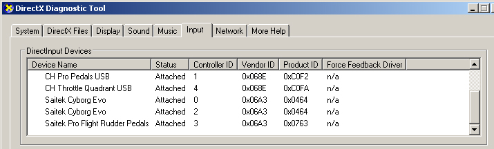
Hi Pete and thanks for your help. I have changed the usb sockects but they still appear in the same order. Then i have applied the lettering and i managed to change the order of joysticks inside of FS but this is not that i want to do. I need to change the order of joysticks inside the windows. I have run the dxdiag and i saw in the inputs tab that the joysticks always they keep a specific id. Do you have any idea how i will modify this?
-
Hi Pete i understand. Nevermind i need your help for another thing i have. I want to change the order of my joysticks in the fsuipc.cfg but when i do this and after i save the file i start the fsx but i still have the joysticks in the order before i change them. Do you know how to do this? Here i have the order of joysticks before and after but i want the second configuration. [JoyNames] AutoAssignLetters=No 0=CH PRO PEDALS USB 1=CH THROTTLE QUADRANT 2=Saitek Cyborg Evo 3=Saitek Pro Flight Rudder Pedals 4=Saitek Cyborg Evo [JoyNames] AutoAssignLetters=No 0=Saitek Cyborg Evo 1=Saitek Cyborg Evo 2=CH PRO PEDALS USB 3=Saitek Pro Flight Rudder Pedals 4=CH THROTTLE QUADRANT
-
Hello Pete this is George again and i need your help now for two things. First i want to assign some buttons assignements of the nd2 of project magenta. I have assign the pilot effis of the airbus through FSUIPC " buttons + swittches " section all the Pm nd section and it is working fine but when i tried to do the same with the Pm nd2 section for the co-pilot none of the buttons is working. I have search as usuall to the "Pm fsuipc offsets" and i have found the following lines: " 04F4 2 Glass Cockpit ND Modes (Write Only) (*was* Read as well) Sending 100+(value) controls First Officer Display (e.g. 170 enables weather on Copilot ND) Only last three digits are used, you can use the thousands to indicate the key has been pressed again (state change), i.e. 2150 and 5150 do the same Please note, these commands go directly to the Glass Cockpit, if you do not want the MCP or FCU to override them, then please use the MCP commands in 0x4F2 or 0x5520. (Values, not bits!) Airbus 1 MAP (Captain Side, 101 F/O side) 2 NAV (Captain Side, 102 F/O side) 3 VOR (Captain Side, 103 F/O side) 4 PLAN (Captain Side, 104 F/O side) 5 ILS Mode Boeing 'Classic Modes' 1 MAP ARC 2 MAP CTR 3 VOR 4 MAP PLAN New ND Modes (!) 1 MAP 3 VOR 4 PLN 5 APP 6 CTR Pushbutton 7 Force display to 8 Modes (APP/VOR/MAP/PLN) 8 Show Controls in EICAS/ECAM 9 Hide Controls in EICAS/ECAM 10 PFD/ND -> PFD -> ND (like pressing F4,F1,F2 in GC) 11 PFD/EICAS 70 Show WXR 71 Hide WXR 72 Toggle WXR 73 VORADFL OFF 74 ADFL ON 75 VORL ON 76 VORADFR OFF 77 ADFR ON 78 VORR ON 80 Terrain Display On 81 Terrain Display Off 82 Toggle Terrain Display 83 Terrain Type Change 84 Terrain Colour/Mode Change 85 Terrain Size Change 86 Terrain 3D 90 STA 91 VOR 92 NDB 93 WPT 94 ARPT 95 DATA 96 POS 321 Decrease Synoptic/System Display Page 322 Increase Synoptic/System Display Page Project Magenta FSUIPC Offsets http://www.projectmagenta.com/resources/PMOffsets.html[8/11/2009 9:58:51 πμ] 12 EICAS with Standby 13 EICAS without Standby 14 FPV (Boeing) 15 Standby Displays OFF 16 Sets EICAS on ND in F4 and F5 pages 19 Toggle Controls in EICAS/ECAM 20 Incr Engine Page 21 Decr Engine Page 22 Toggle No Smoking 23 Toggle Seatbelts 24 Toggle Overview Page 25 Toggle RMI/HSI display in Boeing-Type ND MAP ARC 26 Metric Toggle 28/29 ND Mode INC/DEC for Airbus 30 Engine Page (Primary) 0 31 Engine Page 1 32 Engine Page 2 .. 39 Engine Page 9 (if defined) 40 Range 5 NM (added Aug 27 '03) 41 Range 10 NM 42 Range 20 NM 43 Range 40 NM 44 Range 80 NM 45 Range 160 NM 46 Range 320 NM 47 Range 640 NM 48 Range DEC 49 Range INC 50 TCAS Off 51 TCAS Alt 52 TCAS Callsign 53 TCAS All 54 Toggle TCAS Off/Alt 55 Show MCP Values in EICAS (Boeing) (Special PFC Display) 56 Hide MCP Values in EICAS (Boeing) (Special PFC Display) 57 PLAN mode next waypoint 58 PLAN mode previous waypoint 60 Show Overview Page in ND 61 Hide Overview Page in ND 62 Set/Reset Timer (AB Glass Cockpit) Boeing 737 331 - 336 Upper Engine page direct selection 340 Increment Upper Engine page by 1 (Airbus) Secondary EICAS pages and functions AB 301 ENG 302 BLEED 303 PRESS 304 ELEC (A330/340 EL/AC) 305 HYD 306 FUEL 307 APU 308 COND 309 DOOR 310 WHEEL 311 F/CTL 313 ALL 314 CLR 315 STS 316 RCL 317 CLR 318 EL/DC (A330/340) 319 C/B (A330/340) (Boeing) Secondary EICAS pages and functions 747 301 ENG 302 STAT 303 ELEC 304 FUEL 305 ECS 306 HYD 307 DRS 308 GEAR 318 CANC 319 RCL (Boeing) Secondary EICAS pages and functions 777 301 ENG 302 STAT 303 ELEC 304 HYD 305 FUEL 306 AIR 307 DOORS 308 GEAR 309 FCTL 318 CANC 319 RCL (Boeing) 401 Caution On (see 0x4FE) 402 Caution Reset 411 Show FuelUsed Toggle 412 ShowFuelUsed On 413 ShowFuelUsed Of 414 Reset FuelUsed = 0 (Both) 421 Toggle No Smoking 422 No Smoking On 423 No Smoking Off 424 Toggle Seatbelts 425 Seatbelts On 426 Seatbelts OfF Main Boeing-Type Display Unit Captain Captain Main DU 600 + switch position from 0 Copilot Main DU 610 + switch position from 0 Captain Engine DU 620 + switch position from 0 Copilot Engine DU 630 + switch position from 0 Works on F6 page Expanded Airbus Page Switch 601 Captain PFD/ND normal 602 Captain PFD/ND switched 621 Copilot PFD/ND normal 622 Copilot PFD/ND switched If i have understand corect i must put the 04F4 and for the mask the value of 101 for the F/O side? I dont't now how to do this and i have also download the fsuipc sdk but to tell you the truth i didn't understand anything. I am civil engineer in real life but in programing i know less than a kid so can you send me a tutorial based on fsuipc offsets if i have the offset and the size of any button that i want to assign how i will determine the correct mask for this each time? I am asking you this because i don't want to bother you any time i will have the same difficulties.
-
Hello Pete i need your help again for a problem i have. I have downloaded the "easyFBW" module from < www.stallflyers.com > and i have put it on a client pc. when i start easyFBW i press a button on joystick to calibrate it and everything working fine. Now when i start FS i go to FSUIPC buttons assignements and i can configure all buttons of my joystick which is running on the client pc but when i go to axxis assignements i press rescan, i move an axxis on joy but it has not recognize it at all. Please help me of how i can assign axis through the clients. I have have read all the doc's of FSUIPC and WIDEFS but i havent found any relevant post.
-
Hello Pete i have did as you told me and everything works perfect. Thanks.
-
Hi Pete i had so much work to do with my bussines so i didn't been able to work with FS for some days. Now in the previous post i forgot to mencion that i had allready put the GPSout.dll and the GPSout config inside the modules folder of FS9 but nothing happens. I had also put to the FSUIPC config file these lines: GPSoutEnabled=Yes Port=WideFS Speed=4800 Interval=2000 PosTo6Decimal=Yes Sentences=AV400 and as you can understand nothing happens. Please advise.
-
Hi Pete i have used the settings you are giving inside the "WideFS User Guide" and inside the "FSUIPC4 User Guide" and i have set up correctly the Garmin GPS 296 on a wide client pc. The settings i have put in the FSUIPC config section are these : [GPSout] GPSoutEnabled=Yes Port=WideFS Speed=4800 Interval=2000 PosTo6Decimal=No Sentences=AV400 In the wide client config section i have put : [GPSout] Port=COM1 Speed=4800 And everything are working perfect. The secret is not use the usb connection for the GPS with the "Virtual Serial Port Program" but to use the GPS connected to pc directly with the com cable. For the wideclient pc i am using windows xp sp3 x86. Now i am trying to do the same with the FS9 but i have some issues. Inside the FS9 FSUIPC module there is not any "Autosave and GPS out" generall tab so i have copy the settings of the "GPS out" shown above from FCUIPC4 config section to FSUIPC config section but this didn't work. Do i miss something?
-
Hello Pete i did as you told me and everything works perfect. For example for heading i have put the "Offset word cyclic increment and offset word cyclic decrement" with parameter for increment "1/360" and for decrement "1/360" and to FSUIPC config sections to buttons repeats the value "10,10" and the result is a perfect working FCU with low cost. For the other buttons i have used the "Offset sword increment and offset sword decrement " with the appropriate limits. Trully without you the flight simulator it would be "a just another game". Now i have e real Garmin GPS type"296" and i want to connect it to fs if it is possible on a client pc or to the pc running the fs. I have tried to connect it first to a client pc and i have used the "MixW freeware virtual port simulator" beacause my GPS is USB and i have edit both the cofigs of FSUIPC and widefs client but unfortunately this hasn't work at all. My fs pc is win7 ultimate x64 and the client running the GPS is winxp x86. Should i try to run it on fs pc? Should i try to set up the "Eterlogic one" software? If i try this software as i see i must run the x64 edition. Correct? Or what else i must try to do?
-
Hi Pete i read the FCUIPC users guide in the page 33 but i think i must use 1 step per time because for the heading for example i need for increment one increment each time while i keep the button pushed but fast. I saw in your example that you use the value 16383 as a limit. This value i think is for axis but as you understant i want to make button assignement with no limit. So the combination of the two values you give in the example (256/16383) i dont know how they can work for me. I need to put in the parameter (one change of value each time/no limit) with repeats while holding. In the FCUIPC config section in the buttons i have put " Buttons repeat=1,0" because i want one repeat with no delay at all. If you tell me what values i must put to parameter section for heading increase and deacrease and how you get these values i think for the other buttons i can configure by myself. Pc
-
Hello Pete again i contact with the Pm support and they have send me the values for the FCU. "You should write theactual values to these: 5406 2 MCP/FCU IAS Set (Write) 5408 2 MCP/FCU Heading Set (Write) 540A 2 MCP/FCU Altitude Set (Write) 540C 2 MCP/FCU V/S Set (Write) FCU - FPA in 100s, i.e. 0.9 = 90, -1.4 = -140 540E 2 MCP/FCU Mach Set (Write) (72 = 0.72 mach)" Ok i understand that inside the FSUIPC i must put to "Buttons+Switches" section to the right section for the "MCP/FCU Heading Set (Write)" for example the "x5408" to "Offset" tab but what i must put to "Parameter" tab and to " Control sent when button pressed"? Please advise. :?
-
Hello Pete again this is George and i want your help with some buttons assignements in FSUIPC. As i told you before (in a previous topic) i am building the A320 cockpit and i am using the Project Magenta software. I am have trouble with some buttons assignements of the FCU. I have proggramed all switches and buttons of both EFFIS and they are working great but i am having problem with the main FCU. The main FCU has four push-pull rotary encoders which they work for the speed control the heading the altitude and the vertical speed indicator. For example for the heading when i push the rotary encoder it is activated the LNAV mode and when it is pulled it is activated the selected mode ( which means rotate the rotary encoder clockwise the heading increases and when rotated anticlockwise the heading decreases). The same logics is applied for the other three push-pull rotary encoers. Now for the heading control i am using two buttons and one switch instead of using a push pull rotary encoder. i have assign each of the two buttons as push and pull and the swicth which it has left and right positions as heading increasing and deacreasing. I have also for each posistion of the switch (left and right) assign the "repeat while holding" and the result is i have a FCU workingbut with slow increaments and decreaments. What i must do for these values to inrease and decrease fast while holding the swicth left or right? I have seen inside the FSUIPC that you offer fast increase or decrease for the heading in autopilot but this has'nt work for me beacause i am using specific software (Project Magenta). I will waiting for your reply. Continue the great work. Many thanks.
-
Hello Pete this is George again and i want for first to thank you for your help in my previous problem. I just want tos ask you now do you plan any compatibility for the FSUIPC with the x-plane?
-
PM Airbus co-pilot EFFIS control
sxa1376 replied to sxa1376's topic in FSUIPC Support Pete Dowson Modules
Hello Pete about the x4 i put in parameter i though that in bit 2 as you wrote is 2x2=4 so i thought in parameter for the bit 2 must put x4 -
PM Airbus co-pilot EFFIS control
sxa1376 replied to sxa1376's topic in FSUIPC Support Pete Dowson Modules
Hello Pete and thanks one more time for your help. I need your help for this because as i told you i am amateur in programming and i really don't understand how to deal with bit numbers. I saw in user guide but i steel can not understand how to use these. I have assigned a range for examle in left throttle and i have put to control tab " Offset Byte Togglebits " and to offset " x541C" ( i want to assigne toga function) and to parameter i put "x4" but it didn't work. I think i missing something in parameter tab and for examle in bit 7 how you get value 128?. i understand that bit 2 is 2x2=4 but bit 7 7x2=128? Please advise. -
PM Airbus co-pilot EFFIS control
sxa1376 replied to sxa1376's topic in FSUIPC Support Pete Dowson Modules
Hello Pete and thanks for your interest to help. Forgive my English i don't know them very well so i have problem to describe exactly my problem. I will try to be as descriptive as my knowlidge in Enlgish permits. I have assigne the two throttle levers through FSUIPC axis assignement section as throttle 1 and throttle 2 ( i am building the a320 cockpit). Now in FSUIPC joystick calibration section in one page for example you have the calibration options for the flaps and any one can fix the flaps in detencies ( i think this translated in ranges). The airbus aircraft has the throttle levers working not as full axes but each throttle lever has divided in detencies ( ranges) as the flaps calibration you provide in page 6 ( FSUIPC joystick calibration). I want if you can to help me assign each throttle axis in detencies as in airbus philosophy ( i mean in defferent gates positions : TOGA, FLX, CLB, IDLE, MINREV, MAXREV). Remember as i wrote you before that i am an amateur in programming and a tutorial would be very helpfull. Thank you very much for your time. -
PM Airbus co-pilot EFFIS control
sxa1376 replied to sxa1376's topic in FSUIPC Support Pete Dowson Modules
Hello Pete again i want your assistance for setup the throttles for the A320. Here i am sending you the PM offsets the each of throttle positions. OFFSET SIZE READ - WRITE 541C 4 Airbus THR TOGA Bit 26 THR FLX/MCT Bit 27 THR CLB Bit 28 THR IDLE Bit 29 THR REV IDLE Bit 30 (THR MAX REV if the current status id THR IDLE REV) THR MAX REV Bit 31 I would be very greatfull if you could help me with this. I have allready assign the throttle levels into axis asignement section. -
PM Airbus co-pilot EFFIS control
sxa1376 replied to sxa1376's topic in FSUIPC Support Pete Dowson Modules
Hello Pete again i did everything as you describe and everything worked perfect! I want to thank you very much for your help. You are great. -
PM Airbus co-pilot EFFIS control
sxa1376 replied to sxa1376's topic in FSUIPC Support Pete Dowson Modules
Hello again Pete and thank you very much for your time. I have found from PM site the offsets i think they will do the job. Here they coming as follows. OFFSET SIZE USE 5414 4 MCP/FCU Buttons B32-63 (Read/Write) --- Bit12-Bit15 (free) ALS Bit16 (AB LS Button First Officer) ATFP Bit29 (AB TRKFPA Button) 5410 4 MCP/FCU Buttons B00-31 (Read/Write) ---- B13-16 (free) F/D Copilot On B17 F/D Copilot Off B18 Airbus-Type Extensions ALS K149 (AB LS Button) (Copilot) ATFP K061 (AB TRKFPA Button) I think these must be the offsets required for the co-pilot effis to work through fsuipc " button + swithces " section. If you could help me Pete Please use step by step tutorial because i am amateur in programming. Thank you very much. -
PM Airbus co-pilot EFFIS control
sxa1376 replied to sxa1376's topic in FSUIPC Support Pete Dowson Modules
Hello Pete and thank you very much for your attencion. For the pilot effis LS i have assign the " PM AB LS Button " of FSUIPC " BUttons + Switches " section and this toggle the instrument landing switch for the pilot effis. But the problem is that i can't find any button assignement for the instrument landing switch ( this is the terminal name of this button ) for the co-pilot effis. This button it's toggle the flight director on every PFD for the approach. Airbus in each effis has two buttons for the FD one toggles FD on and off and the other button is the LS which is toggle the FD on PFD for the app. I will waiting for your reply. Many thanks.