ckovoor
-
Posts
122 -
Joined
-
Last visited
-
Days Won
4
Content Type
Profiles
Forums
Events
Gallery
Downloads
Everything posted by ckovoor
-
WidevieW (FSX) network-panning using FSUIPC4 and WideFS
ckovoor replied to ckovoor's topic in User Contributions
Hello Reinhard, Okay, so I'm back at my system and have tested things out: (1) Applying the Read-Only attribute to my standard.xml file does generally prevent FSX from reassigning my buttons and axes, but my Saitek Pro-Flight yoke and my Virtual Joystick (Pokeys card?) seem to be exceptions, in that they retain assignments (that I have not made, and that I have previously erased) within the FSX menu, though they are not visible in the standard.xml file. So, as far as my system goes, this method does not seem to work. I cannot fully prevent the reappearance of unwanted assignments by making my standard.xml file Read-Only. (2) So I switched over to using the SimConnect_CameraSetRelative6DOF function. At each CLIENT I auto-started the the following LUA entitled networkrotation.lua to intercept key-presses sent by FSUIPC in response to the KeySend numbers received from WideClient: -- initial values -- lX = 0.0 lY = 0.0 lZ = 0.0 lPitch = 0.0 lBank = 0.0 lHeading = 0.0 -- camera rotations -- function rotate_right () lHeading = lHeading + 11.25 set_eyepoint () end function rotate_left () lHeading = lHeading - 11.25 set_eyepoint () end function rotate_up () lPitch = lPitch + 5 set_eyepoint () end function rotate_down () lPitch = lPitch - 5 set_eyepoint () end function rotate_reset () lPitch = 0.0 lHeading = 0.0 set_eyepoint () end -- set the eyepoint -- function set_eyepoint () ipc.writeStruct( 0x86A0 , "6FLT" , lX , lY , lZ , lPitch , lBank , lHeading ) -- X, Y, Z, P, B, H end -- events -- event.key ( 39, 8, "rotate_right" ) event.key ( 37, 8, "rotate_left" ) event.key ( 40, 8, "rotate_down" ) event.key ( 38, 8, "rotate_up" ) event.key ( 36, 8, "rotate_reset" ) And here are the relevant parts of the FSUIPC.ini: [Auto] 2=Lua networkrotation [LuaFiles] 4=networkrotation So each movement of the hat-switch rotates the heading by +/- 11.25 degrees or the pitch by +/- 5 degrees, while the trigger button resets the original viewpoint. It works perfectly, and there is no more overlap or misalignment between adjacent views as these screenshots taken from a Dash8 Q400 at the gate at VOBL demonstrate: I now suspect that WidevieW also uses this particular Simconnect function to achieve similarly perfect results. So, thank you, Reinhard, for sharing your knowledge and expertise in this area. I absolutely appreciate it! Chakko.
-
WidevieW (FSX) network-panning using FSUIPC4 and WideFS
ckovoor replied to ckovoor's topic in User Contributions
Dear Reinhard, Thank you for two excellent suggestions, which I will be trying out as soon as I can get back to my system. (1) WidevieW-X provides options for rotating the views by an increment of one's choice, and it works flawlessly (i.e. without overlap/misalignment in both yaw and pitch) with both 2-D cockpit and VC views. I have no information about the internal mechanism involved, and do not know whether those involve SNAP or PAN methods. So if I am able to ENABLE CONTROLLERS without suffering any FSX interference in assignments, by applying READ-ONLY to the standard.xml file, then that would solve the problem completely. (2) I did search for information on the Simconnect function: SimConnect_CameraSetRelative6DofByName. This thread: http://forum.simflight.com/topic/79284-simconnect-wrapper/?page=1 and your own: http://forum.simflight.com/topic/80484-simconnect_camerasetrelative6dof-not-working-as-expected/#comment-486203 do refer to FSUIPC offsets 86A0 through 86B4. I could not find these in the FSUIPC4 offsets list, so I am not certain they will work with FSX, as they seem to have been written for P3D. Perhaps you could enlighten me, since Pete is not here. (3) I also found the FSX controls: VIEW_CAMERA_SELECT_0 66860 VIEW_CAMERA_SELECT_1 66851 VIEW_CAMERA_SELECT_2 66852 VIEW_CAMERA_SELECT_3 66853 VIEW_CAMERA_SELECT_4 66854 VIEW_CAMERA_SELECT_5 66855 VIEW_CAMERA_SELECT_6 66856 VIEW_CAMERA_SELECT_7 66857 VIEW_CAMERA_SELECT_8 66858 VIEW_CAMERA_SELECT_9 66859 VIEW_CAMERA_SELECT_START 66168 which I suppose are linked to the 10 hotkeys. Theoretically, each of these could be assigned a particular view orientation: at best 36 degrees apart (=360/10), and one could cycle through these views using a hat-switch and a related LUA script at each CLIENT. Or perhaps use 8 of these for lateral rotation at 45 degree increments (360/8 = 45) and use the remaining 2 for vertical rotation, say 30 degrees up and 30 degrees down. Would you have any comments on this? Thank you for your interest in this. Chakko. Later: Okay I found this reference https://msdn.microsoft.com/en-us/library/cc526983.aspx#SimConnect_CameraSetRelative6DOF so I guess it should work in FSX after all. Also finally found this in the latest FSUIPC Offsets Status: These are references to the basic CameraSetRelative6DOF function. But the CameraSetRelative6DOFByName function appears to be available only in P3D.
-
WidevieW (FSX) network-panning using FSUIPC4 and WideFS
ckovoor replied to ckovoor's topic in User Contributions
Well, I have been able to sort out issue #1 by editing the Camera.1.13 settings in the .FLT file, thus: [Camera.1.13] Guid={01021987-E220-6507-1024-462840738999} Zoom=2.5567879676818848 Translation=0, 0, 0 Rotation=0, 0, 0 Earlier I was applying an additional rotation of -26 degrees via this setting in the .FLT, when the cameras.cfg had already established an initial heading of -26.0, resulting in a total rotation of -52 degrees on startup. But when I hit the pan_reset button, the view reverted to the initial heading set out in cameras.cfg. The .FLT is apparently referred to only at startup, for initial view orientations. So here we are on startup at Guadelope, with the CLIENT views all perfectly aligned: Still searching for a solution to issue #2. If you have experience with FSX cameras and have something to suggest, I am all ears! Chakko.
-
WidevieW (FSX) network-panning using FSUIPC4 and WideFS
ckovoor posted a topic in User Contributions
Hi everyone, and especially WidevieW (FSX) users, A neat additional feature of WidevieW X is the facility to pan the view laterally on the Clients, and also tilt the view downwards or upwards using a hat-switch on the Server. I find this very useful while sitting at the gate at an airport if I want to have a look at the activity around me, on the Climb when I want to have a look down at the terrain, and on Finals, because with the nose-high attitude of some heavy aircraft, one sometimes doesn't get an adequate view of the runway. So this is a great feature.........however, I found that in order to use it you have to ENABLE CONTROLLERS in FSX (i.e. FSX joystick assignments become active). Unfortunately, I have had to to disable that feature in FSX because (1) I make all my assignments through FSUIPC, and (2) although one can delete all the joystick assignments from FSX using the FSX menu or by editing the Standard.xml file, they usually reappear the next flight by some sort of black-magic, and start conflicting with one's FSUIPC assignments. And it is painful to have to delete these assignments from the menu, manually, at the beginning of every flight. .............................................................................................................................................................................................................. Problem: In order to use WidevieW network-panning with a Hat-Switch on the SERVER, one needs to ENABLE CONTROLLERS in FSX. However, FSX has the nasty habit of randomly rearranging joystick assignments, so many users have switched to using FSUIPC exclusively to manage controllers, and so they DISABLE CONTROLLERS in FSX permanently. This however means that WidevieW's network-panning facilities will not be available any more. Objective: With FSX CONTROLLERS DISABLED on the WidevieW SERVER, to be able to transmit view-panning commands to networked WidevieW CLIENTS. Requirements: Registered FSUIPC4 and WideFS Summary of Process: When a panning-command (via Hat-Switch button) is applied at the SERVER, FSUIPC-WideServer sends a KeySend number to all networked Clients. At each CLIENT, WideClient-FSUIPC receives the KeySend number and acts on it to pan the view locally. Certain options in the wideviewx.ini file at the CLIENTs and SERVER need to be set to ensure that it does not interfere. A new Camera Definition is also installed on the CLIENT(s) to keep this option separate. ______________________________________________________ (1) The WidevieW SERVER will require FSUIPC4 and WideFS-WideServer (both registered). On each WidevieW CLIENT we need to install FSUIPC4 and WideFS-WideClient as well (and because FSX is also running there we need to use a different Class Instance = 1). So the first few lines of the [Config] Section of each WideClient.ini looks like this: [Config] ServerName=SERVER Protocol=TCP ButtonScanInterval=20 ClassInstance=1 NetworkTiming=5,1 MailslotTiming=2000,1000 PollInterval=2000 Port=8002 Port2=9002 : Note that each WideClient is linked to the SERVER FSUIPC (2) On the SERVER, we set up the Hat-Switch to send KeySend numbers across the network (to activate panning at the the Clients). Here are the relevant entries in my FSUIPC.ini file on the SERVER, showing 5 buttons on my Sidewinder Joystick [left, right, up, down and trigger (for reset)] mapped to KeySends 2 through 6. [Buttons] 43=RL,32,C1006,5 -{KEYSEND 5 for WideFS}- 44=RL,34,C1006,2 -{KEYSEND 2 for WideFS}- 45=RL,36,C1006,6 -{KEYSEND 6 for WideFS}- 46=RL,38,C1006,3 -{KEYSEND 3 for WideFS}- 47=PL,0,C1006,4 -{KEYSEND 4 for WideFS}- (3) On each CLIENT, WideClient must receive these KeySend numbers, and transmit the mapped keystrokes to FSX-FSUIPC locally, so the WideClient.ini file at each Client has the following entries in its [User] section. [User] KeySend2=39,8,FS98MAIN KeySend3=37,8,FS98MAIN KeySend4=36,8,FS98MAIN KeySend5=38,8,FS98MAIN KeySend6=40,8,FS98MAIN I have mapped the KeySends to the arrow (l/r/u/d) and home keys. Using FS98MAIN ensures that the keystrokes are sent to the FSX window. (4) FSUIPC residing on the CLIENT must be primed to receive these keystrokes from WideClient, and send the appropriate FSX panning command (controls) to the local FSX via the [Keys] section: [Keys] 12=39,8,65672,0 -{Right: Press=PAN_RIGHT }- 13=37,8,65671,0 -{Left: Press=PAN_LEFT }- 14=36,8,65875,0 -{Home: Press=PAN_RESET }- 15=38,8,65735,0 -{Up: Press=PAN_DOWN }- 16=40,8,65734,0 -{Down: Press=PAN_UP }- Here each keystroke is mapped to a Standard FSX (panning) control: I got these from Pete's reference sheet. (5) Okay, but we also need to ensure that WidevieW will not try to do the same thing. Since I came from a setup where WidevieW was previously doing the network-panning, I needed to go back into the wideviewx.ini file (on each Client) and change a few entries, till each airplane's section looked like this: [WidevieW_Dummy Dash8-Q400] ApplyCurrent=1 ApplyGlobal=0 RaiseLG=1 RaiseLGBy=18 p_headingdelta=45 p_pitchdelta=30 p_setviewangle=0 p_processreorientation=0 p_pitch=0 p_pitchf=0 p_heading=0 p_headingf=0 p_deltax=0 p_deltaxf=0 p_deltay=0 p_deltayf=0 p_deltaz=0 p_deltazf=0 The crucial lines are: p_setviewangle=0 p_processreorientation=0 This ensures that WidevieW will not manipulate the view on the CLIENT, except for locating the aircraft correctly (which is its basic job). I did this for each airplane individually, rather than globally; above is my extract for the Majestic Dash 8 left-side-view Client. Additionally within wideviewx.ini on the Wideview SERVER I set: [Views] HatEnableServer=0 HatEnableClient=0 to ensure no panning commands are sent out by WidevieW (6) I also created a new Camera Definition and added it to the cameras.cfg on each CLIENT. This is because I wanted to keep this new technique separate from the old method: [CameraDefinition.999] Title = "WidevieW Virtual Cockpit" Guid = {01021987-E220-6507-1024-462840738999} Description = Specialised virtual cockpit view. Origin = Virtual Cockpit MomentumEffect = No SnapPbhAdjust = Swivel SnapPbhReturn = False PanPbhAdjust = Swivel PanPbhReturn = False InitialPbh = 0.0, 0.0, -26.0 Track = None ShowAxis = YES AllowZoom = TRUE InitialZoom = 0.7 SmoothZoomTime = 2.0 ZoomPanScalar = 1.0 ShowWeather = Yes XyzAdjust = TRUE ShowLensFlare=FALSE Category = Cockpit PitchPanRate=30 HeadingPanRate=75 PanAcceleratorTime=0 HotKeySelect=4 You will note that the Client's view must be a Virtual Cockpit view for the panning to work correctly. The initialPbh value shows that this is the left view at -26 degrees from centre. I found the following documents helpful to understand camera definitions: http://www.fstipsandaddons.com/tutorials/understanding-fsx-cameras.html https://msdn.microsoft.com/en-us/library/cc526984.aspx#CameraConfigurationFileFormat (7) I use saved flights for each WidevieW Client airplane. So for the Dash8 saved flight (.FLT) I ensured that this particular camera view was linked: [Main] Title=WVD D8Q400test Description="" AppVersion=10.0.61472 FlightVersion=1 [Window.1] Order=0 Active=True Undocked=False Maximized=True ScreenUniCoords=0, 0, 8191, 2600 UndocCoords=0, 0, 0, 0 CurrentCamera={01021987-E220-6507-1024-462840738999} : : [Camera.1.13] Guid={01021987-E220-6507-1024-462840738999} Zoom=2.5567879676818848 Translation=0, 0, 0 Rotation=0, -26, 0 There are a couple of issues I need to iron out, and I think they relate to the settings in my cameras.cfg: (1) I find that when I start a flight, the views are sometimes disorganized or not matched, on the clients, and I do need to press the pan-reset button once at the start to organize all the view angles correctly. With my native WidevieW setup this was not necessary. (2) When I pan or tilt through large angles, I sometimes find adjacent views overlapping slightly or slightly misaligned....this points to the incremental angles not being uniformly applied. I am not sure whether this is a limitation of the panning method chosen (Swivel) or whether it is due to some incorrect setting. Regards, Chakko.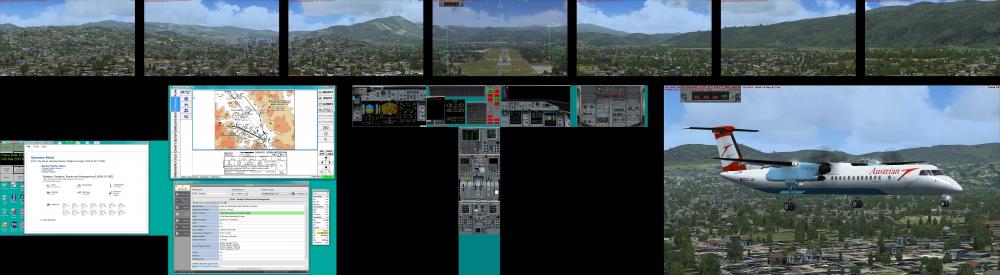
-
Hi Roman, Thank you for sharing your marvellous lua script, and for introducing me to IrfanView. I have used your script in combination with Input Director macros to create (composite) panoramic screenshots of my networked FSX system comprising 7+1+7+3=18 screens. I have sent you a PM with links. Regards Chakko.
- 2 replies
-
- 1
-

-
- Lua
- Screenshot
- (and 1 more)
-
Hello Pete, While attempting to use a rotary encoder to emulate the Bank Angle Selector for a PMDG B777 hardware MCP, I discovered: (1) We have: EVT_MCP_BANK_ANGLE_SELECTOR (SDK value = 2181, Event ID = 71813) and possible Mouse Flags for mouse simulated events: MOUSE_FLAG_RIGHTSINGLE = 2147483648 MOUSE_FLAG_LEFTSINGLE = 536870912 MOUSE_FLAG_WHEEL_UP = 16384 MOUSE_FLAG_WHEEL_DOWN = 8192 (2) Sending the Control 71813 with parameters 8192 and 16384 has no effect. Sending the Control 71813 with parameter 536870912 (LEFTSINGLE) duly causes a decrement in the bank angle selected (as would a left-click on the screen location of the selector). However, FSUIPC will NOT accept the parameter 2147483648 (RIGHTSINGLE) even though the PMDG 777 bank angle selector does itself respond to right-clicks (... it increments the selected bank angle). I tried using the FSUIPC box in the FSX add-ons menu, and also writing it into the fsuipc.ini file, but FSUIPC overwrites it with the value 2147483647. Would you be able to tell me why this happens? (3) After some experimentation, I found that sending the control 71813 with the parameter 256 has the desired effect...i.e. MOUSE_FLAG_RIGHTSINGLE, and so I am able to achieve my aims. Would you be able to explain why the parameter 256 produces the same effect that 2147483648 should have? (I am guessing it has something to do with powers of 2, and storage limitations linked thereto.... :???:) Thank you for your time and patience, and for all you do to support our hobby. :) Warm Regards, Chakko.
-
Hi Pete, I am having a problem with reading bit flags for certain COMM receivers on the Audio Control Panel. They are described in the Offset Mapping for PMDG777X document: Okay, so I understand that 65B8 is reserved for Capt, 65B9 for F/O and 65BA for Observer. But each of these offset (bytes) contain only 8 bits, so how could I read bits 9 through 13 (flags for receivers 8 through 12)? In fact, if I try to read one of these, as for example bit flag 9 below, I do not get any return (as I would expect, since UB can only go as far as 255 :???: ): function COMM_Rcvr_Switch_FO_SAT1(offset, value) if logic.And(ipc.readUB("65B9"), 256) ~= 0 then ipc.writeLvar("L:COMM_Rcvr_Switch_FO_SAT1", 1) else ipc.writeLvar("L:COMM_Rcvr_Switch_FO_SAT1", 0) end end event.offset("65B9", "UB", "COMM_Rcvr_Switch_FO_SAT1") I should mention that I can read the first 8 bit flags with this method. Would you please clarify this for me? My understanding is that a particular offset (byte) can contain a maximum of 8 bit flags, but the documentation indicates 13 within each. Thanks for your help. Chakko.
-
Hi Pete, I have another question about all this......could (event.com + com.getHidButtons) be used instead of (event.timer + com.readlast) to read the button/encoder inputs? I tried running this: Vendor = 0x03EB Product = 0x2043 Device = 0 Report = 0 dev, rd, wrf, wr, init = com.openhid(Vendor, Product, Device, Report) if dev == 0 then ipc.log("Could not open HID") ipc.exit() end buttons = {} -- Up to 256 buttons = 8 x 32 bit words function Poll(dev, CurrentData, rd) -- Now handle the buttons : up to 256 of them! buttons[1], buttons[2], buttons[3], buttons[4], buttons[5], buttons[6], buttons[7], buttons[8] = com.GetHidButtons(dev, CurrentData) -- ignore first 32 buttons by setting i = 2 i = 2 while i <= 8 do -- Send to FSUIPC as a set of 32 virtual buttons -- i.e. DWORD offsets 3340 onwards ipc.writeUD(0x3340 + ((i-1) * 4), buttons[i]) i = i + 1 end end event.com(dev, rd, rd, "Poll") and while FSUIPC did not complain, it didn't work.......button presses in the virtual joystick range were not being recorded. Could you please tell me why. Thanks again for your time and patience.......I absolutely appreciate it! Regards, Chakko.
-
Hi Pete, Thanks for the explanation and the solution. I set i = 2 in the lua and of course it works cleanly.......Arduino physical buttons (1 to 32) are uniquely mapped to the range (Joy#T:Btn#0 to Joy#T:Btn#31), and physical buttons (33 to 256) are uniquely mapped to (Joy#65:Btn#0 to Joy#71:Btn#31). All very neat and predictable, and no dual mappings. Thank you! You imply that it is also possible to prevent Arduino being installed as a joystick (and so have it operated solely via Lua). How would this be achieved? Some might prefer that solution as then we would have one device (with 256 buttons), rather than two (with 32 + 224). Thank you so much for your help! Chakko.
-
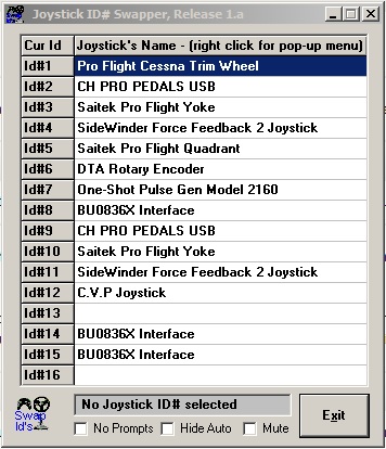
Hi Pete, Thank you very much for taking so much time out to deal with this oddity ..... my own hunch is that you are right about some duplication of sent data at the firmware level. The firmware was written by overpro (who chipped in briefly earlier) and I will request him to tell us more about what is happening there. As for the C.V.P Joystick, that is the Arduino itself! Once the firmware (various files created by overpro) is loaded onto the Arduino, that is the new name under which Arduino seems to announce itself to the various joystick testers available (including the Windows 7: Devices and Printers listing). I am sure overpro can tell us more about the origin of that name. :???: Here is a screenshot of the JoyID scan: in which you can see the Arduino as C.V.P Joystick (Id#12) I have also attached the complete log from HiDScanner, but here the only reference to the Arduino is: ********* HidScanner, Version 2.00 by Pete Dowson ********* Device at "\\?\hid#vid_03eb&pid_2043&mi_00#8&392dae83&0&0000#{4d1e55b2-f16f-11cf-88cb-001111000030}" Vendor=03EB, Product=2043 (Version 0.3) Manufacturer= Arduino Product= 001 Serial Number= C2 Usage Page: 1 Input Report Byte Length: 49 Output Report Byte Length: 0 Feature Report Byte Length: 0 Number of Link Collection Nodes: 2 Number of Input Button Caps: 1 Number of InputValue Caps: 8 Number of InputData Indices: 264 Number of Output Button Caps: 0 Number of Output Value Caps: 0 Number of Output Data Indices: 0 Number of Feature Button Caps: 0 Number of Feature Value Caps: 0 Number of Feature Data Indices: 0 Buttons range 1 -> 256 at indices 8 -> 263 Value Dial at index 0, range 0 -> 65535, using 16 bits Value Sldr at index 1, range 0 -> 65535, using 16 bits Value R/RZ at index 2, range 0 -> 65535, using 16 bits Value V/RY at index 3, range 0 -> 65535, using 16 bits Value U/RX at index 4, range 0 -> 65535, using 16 bits Value Z at index 5, range 0 -> 65535, using 16 bits Value Y at index 6, range 0 -> 65535, using 16 bits Value X at index 7, range 0 -> 65535, using 16 bits ************************************************************************** There does not appear to be a separate reference to its other avatar C.V.P Joystick here (unless I have missed it). I have many many more USB devices, and they are almost all connected to the PC via powered USB hubs, as is the Arduino. The powered hubs have not so far given me any trouble in terms of dropped or swapped USB connections. However, I will try to play with those connections and get back to you. Thank you again for your patience and encouragement! Chakko. HidScanner.txt
-
Hi Pete, Here is the FSUIPC log, in case that helps: ********* FSUIPC4, Version 4.947d by Pete Dowson ********* Reading options from "E:\Microsoft Flight Simulator X\Modules\FSUIPC4.ini" Running inside FSX on Windows 7 Module base=5C3F0000 User Name="Chakko Kovoor" User Addr="xxxxx@xxx.xxx.xxx" FSUIPC4 Key is provided WideFS7 Key is provided 31 System time = 21/10/2015 00:48:48 31 FLT UNC path = "\\SERVER\Flight Simulator X Files\" 842 Trying to connect to SimConnect Acc/SP2 Oct07 ... 858 FS UNC path = "\\SERVER\Microsoft Flight Simulator X\" 1170 ---------------------- Joystick Device Scan ----------------------- 1170 Product= 001 1170 Manufacturer= Arduino 1170 Vendor=03EB, Product=2043 (Version 0.3) 1170 Serial Number= C2 1170 Product= SideWinder Force Feedback 2 Joystick 1170 Manufacturer= Microsoft 1170 Vendor=045E, Product=001B (Version 10.0) 1170 Serial Number= 1170 Product= SideWinder Force Feedback 2 Joystick 1170 Manufacturer= Microsoft 1170 Vendor=045E, Product=001B (Version 10.0) 1170 Serial Number= 1186 Product= CH PRO PEDALS USB 1186 Manufacturer= CH PRODUCTS 1186 Vendor=068E, Product=00F2 (Version 0.0) 1186 Serial Number= 1186 Product= CH PRO PEDALS USB 1201 Manufacturer= CH PRODUCTS 1201 Vendor=068E, Product=00F2 (Version 0.0) 1201 Serial Number= 1201 Product= Saitek Pro Flight Yoke 1201 Manufacturer= Saitek 1201 Vendor=06A3, Product=0BAC (Version 3.3) 1201 Serial Number= 1201 Product= Saitek Pro Flight Yoke 1201 Manufacturer= Saitek 1201 Vendor=06A3, Product=0BAC (Version 3.2) 1201 Serial Number= 1201 Product= Pro Flight Cessna Trim Wheel 1201 Manufacturer= Saitek 1201 Vendor=06A3, Product=0BD4 (Version 1.6) 1201 Serial Number= RD001180 1201 Product= Saitek Pro Flight Quadrant 1201 Manufacturer= Saitek 1201 Vendor=06A3, Product=0C2D (Version 2.0) 1201 Serial Number= 1201 Product= DTA Rotary Encoder 1201 Manufacturer= Desktop Aviator 1201 Vendor=16C0, Product=27CB (Version 1.33) 1201 Serial Number= A12057 1201 Product= One-Shot Pulse Gen Model 2160 1201 Manufacturer= Desktop Aviator 1201 Vendor=16D0, Product=0484 (Version 0.1) 1201 Serial Number= DTA00271 1201 Product= BU0836X Interface 1201 Manufacturer= Leo Bodnar 1201 Vendor=1DD2, Product=1001 (Version 1.35) 1217 Serial Number= B14857 1217 Product= BU0836X Interface 1217 Manufacturer= Leo Bodnar 1217 Vendor=1DD2, Product=1001 (Version 1.35) 1217 Serial Number= B20455 1217 Product= BU0836X Interface 1217 Manufacturer= Leo Bodnar 1217 Vendor=1DD2, Product=1001 (Version 1.35) 1217 Serial Number= B20453 1217 ------------------------------------------------------------------- 2044 Run: "C:\Program Files (x86)\IObit\Game Booster 3\GameBooster.exe -game" 2449 Run: "C:\Program Files (x86)\SPAD\Spad.exe" 2699 Run: "C:\Program Files (x86)\CH Products\CMStart.exe" 2792 Run: "C:\Program Files (x86)\WinLayoutManager\WinLayoutManager.exe" 3416 Run: "E:\Microsoft Flight Simulator X\FsRaas20\FsRaas20.exe" 3526 Run: "E:\ToggleIDMacros.exe" 3760 Run: "C:\Program Files (x86)\AivlaSoft\EFB\AivlaSoft.Efb.DataProvider.exe" 4196 Run: "E:\PILOTS_FSGRW_NETWORKBRIDGE\FS Global Real Weather Network Bridge.exe" 4633 Run: "C:\Windows\System32\cmd.exe /c "net stop "audiosrv" & net start "audiosrv"" 4633 LogOptions=00000000 00000001 4649 ------------------------------------------------------------------- 4649 ------ Setting the hooks and direct calls into the simulator ------ 4649 --- CONTROLS timer memory location obtained ok 4649 --- SIM1 Frictions access gained 4649 --- FS Controls Table located ok 4649 --- Installed Mouse Macro hooks ok. 4649 --- Wind smoothing fix is fully installed 4649 --- G3D.DLL fix attempt installed ok 4649 --- All links checked okay 4649 ------------------------------------------------------------------- 4649 SimConnect_Open succeeded: waiting to check version okay 4649 Trying to use SimConnect Acc/SP2 Oct07 8284 Running in "Microsoft Flight Simulator X", Version: 10.0.61472.0 (SimConnect: 10.0.61259.0) 8284 Initialising SimConnect data requests now 8284 FSUIPC Menu entry added 8315 \\SERVER\Flight Simulator X Files\FSX Startup for Complex Aircraft.FLT 8315 \\SERVER\Microsoft Flight Simulator X\SimObjects\Airplanes\Aircreation_582SL\Aircreation_582SL.AIR 27753 System time = 21/10/2015 00:49:15, Simulator time = 13:30:30 (20:30Z) 28533 Aircraft="Aircreation582SL red" 30171 Starting everything now ... 31512 Advanced Weather Interface Enabled 694080 Sim stopped: average frame rate for last 500 secs = 22.7 fps 725919 Sim stopped: average frame rate for last 21 secs = 75.9 fps Thanks, Chakko.
-
Hi Pete, Let me review this, to make sure you have understood the scenario, as I may not have been very clear. There is only one physical USB joystick suffering the conflict in this case: the Arduino Mega configured as a USB-HID rather than as a USB-COM device. Here is the full FSUIPC.ini JoyNames section......I had omitted the irrelevant parts earlier [JoyNames] AutoAssignLetters=Yes 1=CH PRO PEDALS USB 1.GUID={DBCB2B40-097E-11E1-8002-444553540000} 2=Saitek Pro Flight Yoke 2.GUID={DBCB2B40-097E-11E1-8003-444553540000} 4=Saitek Pro Flight Quadrant 4.GUID={DBCB2B40-097E-11E1-8005-444553540000} A=CH PRO PEDALS USB A.GUID={DBCB2B40-097E-11E1-8002-444553540000} B=Saitek Pro Flight Yoke B.GUID={DBCB2B40-097E-11E1-8003-444553540000} C=Saitek Pro Flight Quadrant C.GUID={DBCB2B40-097E-11E1-8005-444553540000} D=BU0836X Interface E=One-Shot Pulse Gen Model 2160 F=BU0836X Interface F.GUID={05EBBDE0-5281-11E1-8001-444553540000} G=CH PRO PEDALS USB H=Saitek Pro Flight Yoke 3=SideWinder Force Feedback 2 Joystick 3.GUID={B2C832F0-261C-11E1-8001-444553540000} J=SideWinder Force Feedback 2 Joystick J.GUID={B2C832F0-261C-11E1-8001-444553540000} K=Pro Flight Cessna Trim Wheel K.GUID={DBCB2B40-097E-11E1-8004-444553540000} L=SideWinder Force Feedback 2 Joystick D.GUID={247DEDD0-2127-11E2-8001-444553540000} G.GUID={52390D80-C921-11E1-8001-444553540000} M=Virtual Joystick M.GUID={5C04E460-3A2D-11E2-8001-444553540000} 10=SideWinder Force Feedback 2 Joystick 10.GUID={FC327BD0-CC5C-11E1-8001-444553540000} 8=CH PRO PEDALS USB 8.GUID={52390D80-C921-11E1-8001-444553540000} 9=Saitek Pro Flight Yoke 9.GUID={5287F0D0-C921-11E1-8002-444553540000} N=BU0836X Interface N.GUID={B964AF70-7EA3-11E4-8001-444553540000} 5=DTA Rotary Encoder 5.GUID={DBCB2B40-097E-11E1-8008-444553540000} 6=One-Shot Pulse Gen Model 2160 6.GUID={DBCB2B40-097E-11E1-8009-444553540000} 7=BU0836X Interface 7.GUID={05EBBDE0-5281-11E1-8001-444553540000} X=<< MISSING JOYSTICK >> 0=Pro Flight Cessna Trim Wheel 0.GUID={DBCB2B40-097E-11E1-8004-444553540000} P=BU0836X Interface P.GUID={5CF9E380-06C6-11E5-8001-444553540000} 13=BU0836X Interface 13.GUID={247DEDD0-2127-11E2-8001-444553540000} Q=DTA Rotary Encoder Q.GUID={DBCB2B40-097E-11E1-8008-444553540000} 14=BU0836X Interface 14.GUID={B964AF70-7EA3-11E4-8001-444553540000} R=One-Shot Pulse Gen Model 2160 R.GUID={EB0D3BD0-1C07-11E5-8001-444553540000} S=Virtual Joystick S.GUID={5C04E460-3A2D-11E2-8002-444553540000} 11=C.V.P Joystick 11.GUID={6EDD62E0-6079-11E5-8001-444553540000} T=C.V.P Joystick Yes, I do have all those devices connected! :oops: Okay, so if I start FSX with the Arduino connected (but without the lua plugin running), and open the FSUIPC dialog window to the Buttons + Switches tab, and operate any of the first 32 buttons on the Arduino, I will see FSUIPC responses ranging from Joy#T:Btn#0 to Joy#T:Btn#31. There is no conflict at this stage. If I operate physical buttons beyond the first 32 , say # 56, I do not see any response in the FSUIPC window. Now, I go back into FSX and start the lua plugin. Then I return to the FSUIPC dialog box - Button + Switches tab. This time when I operate any of the first 32 buttons on the Arduino, I see either Joy#T or Joy#64 flash alternately in the Joy# window (but the same number in the Btn# window). So now the Arduino hardware seems to have a dual mapping to both Joy#T and Joy#64 (which was of course a virtual joystick created by the lua plugin). These conflicts occur for the first 32 buttons only, but not thereafter. From the 33rd Arduino button onwards, Joy#T does not appear anymore in the Joy window, only the appropriate virtual Joy#(65 to 71). I tried changing the offset base to 0x3344 in the lua plugin, but all that did was to make the virtual Joy#'s start from 65 rather than 64. Conflicts still occur with Joy#T for the first 32 buttons. If by the JoyID's utility you mean HiDScanner, then I have already run that to discover the Arduino data which needed to be inserted into the lua. Thank you again for your patience and encouragement. :razz: Regards, Chakko.
-
Hi Pete, Well, before I run the lua plugin, FSUIPC sees only joystick T with 32 buttons, and there is no conflict. The virtual joystick buttons (starting at Joy#64:Btn#0) appear only after I start the lua plugin. So the lua plugin is creating all these virtual buttons. And the first 32 of these buttons are mapped to the same hardware as the first 32 on joystick T. The conflict would end there since T cannot show more than 32. Is my understanding correct? So then my question would be whether there is any way (perhaps a programmatic way?) of preventing the lua plugin from generating virtual buttons which would be in conflict (or dually assigned) with those from joystick T? Thanks for your patience, Chakko.
-
Hi Pete, While testing the arrangement I found that the first 32 buttons seemed to be recognised by FSUIPC as belonging to two separate joysticks. Here is the relevant extract from the FSUIPC.ini file: [JoyNames] AutoAssignLetters=Yes 1=CH PRO PEDALS USB 1.GUID={DBCB2B40-097E-11E1-8002-444553540000} : : 11=C.V.P Joystick 11.GUID={6EDD62E0-6079-11E5-8001-444553540000} T=C.V.P Joystick So my Arduino Mega is being recognized simultaneously as 11=C.V.P Joystick and T=C.V.P Joystick. I am guessing that the former is a reference to a virtual joystick and the latter is a Windows Game Controller (not sure of the terminology). The consequence of this is that in the FSUIPC window, for the first 32 assignable buttons, I am getting (flashing) dual references (for instance Joy#T:Btn# 0 and Joy#64:Btn#0). There is no problem after the 32nd button.....only the virtual joystick buttons appear after that (Joy#65:Btn#0 onwards). My short term solution is to avoid the first 32 buttons, since I still have the remaining 224. But is there a better solution......to get FSUIPC to recognise the first 32 only one way? Preferably to see those as only belonging to the virtual joystick, for the sake of consistency. Thanks and Regards, Chakko.
-
Hi Pete, Thank you for your response. I have found the problem lay in the code I had used earlier. I had omitted a condition n ~= 0, and I had omitted the init section.....one of these omissions was the culprit. When I inserted both and re-ran the lua, all 256 encoders/buttons were recognised as virtual buttons in the range you have specified in the manual. For reference, here is the working code: Vendor = 0x03EB Product = 0x2043 Device = 0 Report = 0 Pollrate = 25 dev, rd, wrf, wr, init = com.openhid(Vendor, Product, Device, Report) if dev == 0 then ipc.log("Could not open HID") ipc.exit() end buttons = {} -- Up to 256 buttons = 8 x 32 bit words prevbuttons = { 0, 0, 0, 0, 0, 0, 0, 0 } function Poll(time) -- We use "readlast" so the values we use are the most up-to-date CurrentData, n, discards = com.readlast(dev, rd) -- Extract values we need if n ~= 0 then -- Now handle the buttons : up to 256 of them! buttons[1], buttons[2], buttons[3], buttons[4], buttons[5], buttons[6], buttons[7], buttons[8] = com.GetHidButtons(dev, CurrentData) -- check for changes i = 1 while i <= 8 do if buttons[i] ~= prevbuttons[i] then prevbuttons[i] = buttons[i] -- Send to FSUIPC as a set of 32 virtual buttons -- i.e. DWORD offsets 3340 onwards ipc.writeUD(0x3340 + ((i-1) * 4), buttons[i]) end i = i + 1 end end end ------------------------------------------------------------------------ if init then -- Deal with initial values, if supplied (some joysticks don't) ipc.log("init seen!") Poll(0) end if Pollrate == 0 then -- Ouch. Mustn't divide by zero! Pollrate = 25 end event.timer(1000/Pollrate, "Poll") -- poll values 'Pollrate' times per second Thank you once again for FSUIPC-LUA, whose seemingly limitless possibilities never cease to amaze me, and thank you for your patience! Warm Regards, Chakko.
-
Hi Pete, I am experimenting with using an Arduino Mega as a 256-button USB HID joystick under FSX-FSUIPC. HiDScanner duly recognises the device as such: ********* HidScanner, Version 2.00 by Pete Dowson ********* Device at "\\?\hid#vid_03eb&pid_2043&mi_00#8&392dae83&0&0000#{4d1e55b2-f16f-11cf-88cb-001111000030}" Vendor=03EB, Product=2043 (Version 0.3) Manufacturer= Arduino Product= 001 Serial Number= C2 Usage Page: 1 Input Report Byte Length: 49 Output Report Byte Length: 0 Feature Report Byte Length: 0 Number of Link Collection Nodes: 2 Number of Input Button Caps: 1 Number of InputValue Caps: 8 Number of InputData Indices: 264 Number of Output Button Caps: 0 Number of Output Value Caps: 0 Number of Output Data Indices: 0 Number of Feature Button Caps: 0 Number of Feature Value Caps: 0 Number of Feature Data Indices: 0 Buttons range 1 -> 256 at indices 8 -> 263 Value Dial at index 0, range 0 -> 65535, using 16 bits Value Sldr at index 1, range 0 -> 65535, using 16 bits Value R/RZ at index 2, range 0 -> 65535, using 16 bits Value V/RY at index 3, range 0 -> 65535, using 16 bits Value U/RX at index 4, range 0 -> 65535, using 16 bits Value Z at index 5, range 0 -> 65535, using 16 bits Value Y at index 6, range 0 -> 65535, using 16 bits Value X at index 7, range 0 -> 65535, using 16 bits ************************************************************************** I use a 16 x 16 matrix to 'create' the various encoders and buttons, and have tested the arrangement partially with SV Mapper (a joystick testing software), so know it works. I run a shortened version of your HidDemo.lua: Vendor=0x03EB Product=0x2043 Device=0 Report=0 Pollrate=25 dev, rd, wrf, wr, init = com.openhid(Vendor, Product, Device, Report) if dev == 0 then ipc.log("Could not open HID") ipc.exit() end buttons = {} -- Up to 256 buttons = 8 x 32 bit words prevbuttons = { 0, 0, 0, 0, 0, 0, 0, 0 } function Poll(time) -- We use "readlast" so the values we use are the most up-to-date CurrentData, n, discards = com.readlast(dev, rd) -- Now handle the buttons : up to 256 of them! buttons[1], buttons[2], buttons[3], buttons[4], buttons[5], buttons[6], buttons[7], buttons[8] = com.GetHidButtons(dev, CurrentData) -- check for changes i = 1 while i <= 8 do if buttons[i] ~= prevbuttons[i] then prevbuttons[i] = buttons[i] -- Send to FSUIPC as a set of 32 virtual buttons -- i.e. DWORD offsets 3340 onwards ipc.writeUD(0x3340 + ((i-1) * 4), buttons[i]) end i = i + 1 end end event.timer(1000/Pollrate, "Poll") -- poll values 'Pollrate' times per second and then test for the encoders and buttons in the FSUIPC window. The trouble is that irrespective of the actual button or encoder that I press/turn, FSUIPC always registers the action as (virtual) Joy# 71:Btn# 1 or Joy# 70:Btn# 1 or Joy# 69:Btn# 24. I have tried all possible buttons and encoders and always get the same result. (I don't know if this is relevant to the issue, but at this stage I have not connected the entire 16 x 16 matrix to the Arduino, but test for a particular button or encoder in the matrix by connecting only the relevant pair of pins. This is not a problem when testing under SV Mapper.) Would you be able to tell me what I am doing wrong? Thanks and Regards, Chakko. (using registered FSUIPC 4947d, FSX-SP2)
-
Assign one button to 2 differrent key presses
ckovoor replied to glennav8r's topic in FSUIPC Support Pete Dowson Modules
Hi Pete, My understanding is that If Glenn needs the second button action called on a 2-second press, and not merely toggle the two button actions, then that would require a time-dependent function, which would require a lua script, in addition to editing of parameters in the .ini file, as we discussed here: http://forum.simflight.com/topic/79641-level-d-b767-mcp-with-lekseecon-f-fsuipc4-pokeys-56u-and-arduino-mega/?p=481683 Regards, Chakko -
Hi Pete, I've been putting the finishing touches to my B767 MCP, and had to make a compromise with the heading selector. The real-world B767 MCP has a Heading knob, integrated with a heading Select button, and a Bank-limit rotary switch selector. I guess 'acceleration' for the heading input is built into the device. But, at present, all I have installed is a single rotary encoder with an integrated push-button switch. So to emulate all the functions of the r-w knob, I decided on the following scheme: (1) Single short press of the push-button toggles between higher and lower value increments/decrements for rotation of the heading knob. (2) Two short presses in quick succession selects the bank-limit control, for which a mouse macro is available to increment or decrement the setting by rotation of the knob. (3) Long press of the push-button is the heading select function, or the equivalent of pressing the pushbutton (marked 'SEL') integrated with real-world knob. I copied the framework of your TripleUse.lua, and modified it, and ran the code, and it works! I am reproducing it here in case it can be of use to anyone else. One little wrinkle still to be ironed out is that while applying a long press (3), the script also seems to apply a short press (1), and toggles the associated bit. joy = "M" btn = 19 interval = 500 -- 1/2 second press, gap, press limits ---------------heading button----------------- local function timebutton(test) while true do time2 = ipc.elapsedtime() if (time2 - time1) > interval then return false end if ipc.testbutton(joy, btn) == test then time1 = time2 return true end ipc.sleep(20) end end function buttonpress(j, b, du) -- Cancel event so we don't get called again for double press event.cancel("buttonpress") -- Note time button was pressed time1 = ipc.elapsedtime() if timebutton(false) then -- First press / release counts: see if there's another if timebutton(true) then -- got another press in time, look for release if timebutton(false) then -- this was a double press, select bank-limit by writing button parameter 2 to offset 66C0 ipc.writeUB(0x66C0, 2) end else -- This was a single press, toggle flag for large/small increment by toggling the bit at offset 66C1 and copy the flag back to offset 66C0 if ipc.readUB(0x66C1) == 0 then ipc.writeUB(0x66C1, 1) else ipc.writeUB(0x66C1, 0) end ipc.writeUB(0x66C0, ipc.readUB(0x66C1)) end else -- This was a longer press, select heading select by writing button parameter 3 to offset 66C0 ipc.writeUB(0x66C0, 3) ipc.sleep(20) ipc.writeUB(0x66C0, ipc.readUB(0x66C1)) end -- Restore cancelled event event.button(joy, btn, 1, "buttonpress") end -----------------events-------------------- event.button(joy, btn, 1, "buttonpress") and the relevant FSUIPC4.ini extract: ; button 17 is encoder turned acw, button 18 is encoder turned cw ; button 19 is integrated push-button 200=B66C0=0 PM,17,Cx63008B1C,x01670001 ;hdg cyclic decrement 1 deg, range 1/359 201=B66C0=1 PM,17,Cx63008B1C,x0167000A ;hdg cyclic decrement 10 deg, range 10/359 202=B66C0=0 PM,18,Cx53008B1C,x01670001 ;hdg cyclic increment 1 deg, range 1/359 203=B66C0=1 PM,18,Cx53008B1C,x0167000A ;hdg cyclic increment 10 deg, range 10/359 204=B66C0=2 PM,17,CM5:100,0 ;mouse macro to decrement bank-limit 205=B66C0=2 PM,18,CM5:101,0 ;mouse macro to increment bank-limit 206=B66C0=3 PM,19,Cx0D00911C,x01 ;pressing hdg SEL knob toggles bit at the lekseecon offset What a fantastic tool you have created in FSUIPC, and what a powerful addition you have brought in with the lua library! I am just scratching the surface of possibilities, I know, but I am constantly amazed at what can be achieved! I was wondering whether the same objectives could have been achieved by direct button programming in the FSUIPC4.ini file. I felt it might not be possible in this case because (i) I wasn't clear about whether one could implement a 'timer-based choice' there, and (ii) a button flag can only toggle between two states, but here we have to choose between three. You will note that I used the free offsets at 66C0 and 66C1 to store the chosen button mode, and that the behaviour of the knob is then conditional on the value of this parameter. Warm regards, Chakko.
-
Thank you, Pete! I can confirm that with FSUIPC4 version 4.939v I am able to set the lower limit at 100 knots on my hardware MCP, as I needed to. Thank you again!
-
Hi Pete, Thank you for your response. I confirm that I am using registered FSUIPC4 version 4.939u. Regards, Chakko.
-
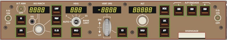
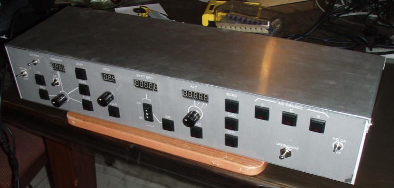
Hi Pete and Nico, I have built a (hardware) B767-300ER MCP to interface with the FSX Level-D B767, using Pokeys 56U for the rotaries and switch inputs and an Arduino Mega 2560 for the annunciators and numeric outputs. I am having a problem with the lower limit of the IAS/MACH input....(the upper limit is working fine). The lekseecon_f manual states: lekseecon var 296: range is 4 bytes (32 bit) -> (FSUIPC offset 0x8b18) read/write -> MCP IAS/Mach, range 100 to 950 Note: Mach values are given x 1000, so .802=802 lekseecon var 296 has been duly activated in my lekseecon.ini file. So, for the rotary encoder controlling IAS/MACH these are the entries in my FSUIPC4.ini file: 195=PM,16,C1005,3840 196=CP(F-15,0)M,14,Cx23008B18,x00640001 197=CP(F+15,0)M,14,Cx23008B18,x0064000A 198=CP(F-15,0)M,15,Cx13008B18,x03B60001 199=CP(F+15,0)M,15,Cx13008B18,x03B6000A Joystick M is my Pokeys card. (195) Button 16 is the pushbutton integrated with the rotary encoder which enables toggling between increments/decrements of 1 knot and 10 knots (or .001 mach and .010 mach). (196) Button 14 (rotary encoder) turned anticlockwise Cx2300 = Offset UDword Decrement, 8B18 = fsuipc offset for ias/mach, x0064 = lower limit of 100 in hex, 0001 = decrement of 1 (197) Button 14 (rotary encoder) turned anticlockwise Cx2300 = Offset UDword Decrement, 8B18 = fsuipc offset for ias/mach, x0064 = lower limit of 100 in hex, 000A = decrement of 10 (198) Button 15 (rotary encoder) turned clockwise Cx1300 = Offset UDword Increment, 8B18 = fsuipc offset for ias/mach, x03B6 = upper limit of 950 in hex, 0001 = increment of 1 (199) Button 15 (rotary encoder) turned clockwise Cx1300 = Offset UDword Increment, 8B18 = fsuipc offset for ias/mach, x03B6 = upper limit of 950 in hex, 000A = increment of 10 Now, this works perfectly on the upper limit....i.e. I can keep turning the rotary encoder cw, but the display will not register anything beyond 950. But, the problem is that it does not work on the lower limit.....i.e. if I keep turning the rotary encoder acw, the display WILL go below 100, in steps of 1 or 10, until it reaches 0. So the lower limit of 100 that I have imposed via the code is not being respected. So, would you please be able to tell me whether I have done something wrong, and how I could set this right? Thanks and Regards, Chakko.
-
Hi Pete, Thank you for your response. I agree that it would be self-defeating in the case of a B737 hardware cockpit. But that is because all the offsets to drive hardware are available, so one doesn't need this 'backdoor solution'. But consider builders who would like to build say an MD-11 cockpit, and see in the PMDG MD-11 software a superlative basis on which to do so, but are confronted by the TOTAL absence of published or 'discovered' offsets. In that case one could use this method: have the FS PC run a couple of monitors displaying the panels from which one extracts the pixel data I am speaking of, and send the information to the hardware cockpit which takes centre-stage. The monitors displaying the FS panels need not be visible at all; they might in fact be running in a corner of the room, out of view! If that is the 'cost' of building an MD-11 hardware cockpit, I feel there would be many builders who would consider it. The lack of published offsets around reasonably detailed add-on aircraft simulations has been, I believe, a major deterrent to building hardware cockpits other than the B737. So, the method proposed is a solution for building hardware around add-on aircraft where offsets for the outputs are not available. (The caveat is that one would need to have a screen running from which the data is to be extracted, and the panel windows cannot be hidden.) Anyway....continuing my work with Arduino-driven hardware, I have successfully run lua plugins which open the COM port and send the required data to the Arduino. All that now remains to integrate this solution fully within FSUIPC is to find a Lua library with functions to read pixel data off the FS screen 'in real-time'. There is a lua package entitled Lua-GD at http://ittner.github.io/lua-gd/manual.html which has a gdImage:getPixel(x, y) function, however, as I understand it, it can only work with pre-loaded images, and not with on-screen displays generally. I have searched elsewhere, but so far have been unsuccessful in locating an appropriate library and function. So if you, or anyone else knows of any such Lua library, or if there is some other way to build this functionality into FSUIPC Lua, I for one will be extremely grateful. :razz: Thank you for your help and patience! Warm regards, Chakko.
-
Hi Pavel, I don't know whether you finally solved your issue with the COM port. Like you, I am trying to establish direct communication between FSUIPC and my Arduino via Lua Com. Anyway, I spent a whole afternoon with your code, and variations of it, experiencing exactly the same issue.....flashing Rx light but no output to the pins..... :???:......until I finally traced the problem......I removed the ipc.sleep(500) line, and the Arduino duly sent its output signals to the LED. :razz: So try removing the ipc.sleep line and see if it works for you too. I've attached my working test code (the sequences 010 and 011 are of course what my Arduino is looking for). Regards, Chakko. dev = com.open("COM3", 115200, 0) function pkgbrake(offset, value) if value == 0 then com.write(dev, "010\n") else com.write(dev, "011\n") end end event.offset(0x0BC8, "UB", "pkgbrake")
-
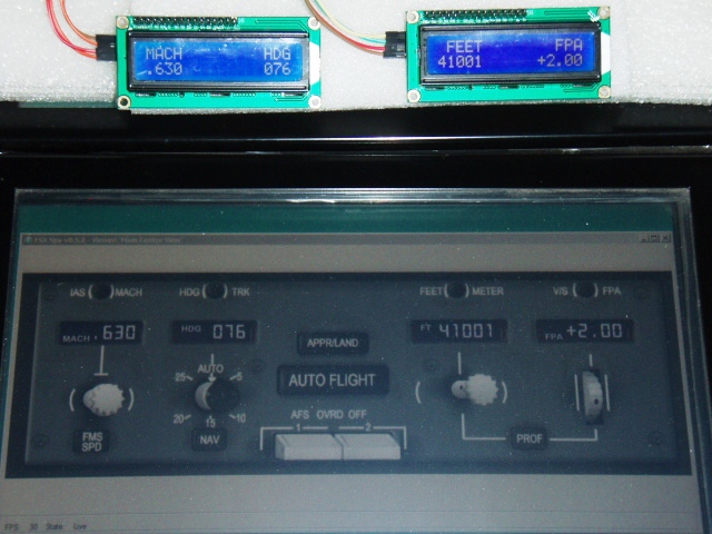
Hi Pete, I have recently started using an Arduino Mega to display outputs from FSX on LED's + 8-digit, 7-segment LED modules + 1602 LCD's. This is to augment (but not replace) my touchscreen-based simulator whose cockpit comprises 2-D panels of payware add-on aircraft across 6 touchscreen monitors. My present project is to construct as many different hardware MCP's as possible. For the inputs I use encoders and switches driven by Bodnar's BU0836X and Pokeys 56U in conjunction with FSUIPC Mouse Macros/aircraft-specific key assignments. This is a robust and stable solution and I will not change it. It is for the hardware MCP outputs (alone) that I am using Arduino. (1) For the PMDG 737 NGX I am using this scheme, made possible by your detailed listing of FSUIPC offsets for the aircraft: PMDG737NGX --> FSUIPC --> Jim's Link2FS --(USB/COM)--> Arduino --> LED's (2) This also worked for the Level-D B767 as Nico Kaan's Lekseecon_f bridges the gap between the aircraft and FSUIPC: LD B767 --> Lekseecon_f --> FSUIPC --> Link2FS --(USB/COM)--> Arduino --> LED's (3) The first challenge came with the SimCheck A300B4. This aircraft uses standard SimConnect variables/FSUIPC offsets for MCP digital outputs of SPD/ALT/HDG etc, so displaying these outputs followed the same scheme as for the NGX. But offsets for the connected annunciator lights are not available. So I took a backdoor route: - wrote an Autoit routine to detect pixel colour at the each on-screen annunciator location (every 100 ms) and assess whether that light was on or off, and write the results as a string to a .txt file - wrote a lua plugin to read that .txt file (every 100 ms), and write the annunciator states to 15 free FSUIPC offsets starting at 0x66C0 - Link2FS was then programmed to read these offsets and transmit them to the Arduino via the USB/COM serial port SC A300B4 --> Autoit --> FSUIPC --> Link2FS --(USB/COM)--> Arduino --> LED's A full description of the method and photographs is at http://www.mycockpit.org/forums/showthread.php?t=28888 The method works, and there is very little lag between the operation of a switch and the response of the hardware. (4) I then started work on the PMDG MD-11X MCP. This MCP has no annunciators as such, but it does have digital readouts. But, as you know, there are no available FSUIPC offsets at all for this aircraft, so I did the following: - wrote an Autoit routine to detect critical pixel colours, one at each segment of each digit of the readouts (every 100 ms) to detect its state, analyze all the information across the 15 digits to produce an 'image' of what digits were displayed, and then transmit this information to the Arduino directly via the COM port. Autoit has advanced window/pixel management functions as well as functions for serial communications, so everything was bundled into one script. Link2FS and FSUIPC are not involved. PMDG MD-11--> Autoit ---(USB/COM)--> Arduino --> LCD's I have attached a photo of the screen version of the MCP and its 'real-time' LCD equivalent (I would have uploaded a video if I had the means to produce a good one). Anyway, it works! And there is no noticeable lag between the parent display and its hardware 'derivation'. (5) My next project will be the PMDG B747-400X MCP.Here the digital readouts are not 7-segment LED's but more like mechanical counters, so I will probably have to analyze more pixel states, and there are illuminated switches to consider as well. So it will be a larger project. The method proposed is a solution for building hardware around add-on aircraft where offsets for the outputs are not available. The caveat is that one would need to have a screen running from which the data is to be extracted, and the panel windows cannot be hidden. I find that this idea has been mooted before, though quite a while ago: http://forum.simflight.com/topic/58052-solution-to-detecting-light-state-changes-in-pmdg-overhead/?hl=%2Bpixel+%2Bcolour I wonder how he has gotten on in the interim. So far I have been using Autoit, and I have to say it works very well. However, FSUIPC does have a (lua) COM library, so communicating with the Arduino is certainly possible. So I am wondering if you might consider adding facilities for pixel analysis (pixel colour detection) at FS window locations via lua. I know that such libraries exist out there, and it would be a boon (to hardware cockpit-builders adopting this method) to be able to handle all this within FS/FSUIPC. It's just my idea, and I look forward to your opinion. Thank you for all that you are doing to support and enhance our hobby. Warm Regards, Chakko.
-
PDMG 737 Pokey 56 E and FS Symphony
ckovoor replied to mlf081161's topic in FSUIPC Support Pete Dowson Modules
Hello Michel (and others who might be interested in using Pokeys 56E/57E with FSSymphony to read PMDG 737NGX offsets), I wonder if anyone has made progress with this, that they might like to share, especially now that v2.0 of FSSymphony introduces an Expert Mode where this might be possible? Thank you for your attention! Chakko.